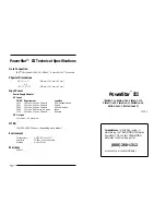

PowerStar™ III
10
9
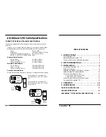
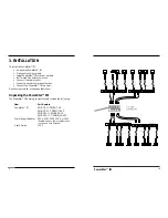
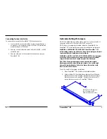
Installing PowerStar™ III in Rack or on Table
NOTE: The 14-port PowerStar™ III is shipped with attached brackets
for standard 19-inch rack installation. All PowerStars™ are shipped
with attachable feet for table-top installation.
To install the PowerStar™ III in 19-inch rack:
1. Locate four (4) screws (NOT PROVIDED) for each PowerStar™
III to be installed.
2. Carefully align the PowerStar™ III at the installation position
between the 19-inch rack mounting rails.
3. Install two screws through right front bracket and two screws
through left front bracket, using clip nuts if necessary.
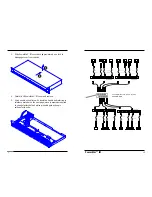
To install the PowerStar™ III on table or other flat surface:
1. Carefully turn PowerStar™ III to side.
2. Install four (4) rubber feet):
•
Remove protective paper from rubber foot adhesive surface.
•
Position rubber foot at bottom corner of repeater hub.
•
Press rubber foot against PowerStar™ III surface to secure.
•
Repeat for remaining rubber feet.
3. Return PowerStar™ III to upright position.
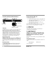
PowerStarIII
Link
0
1
2
3
4
5
6
Line Sync
Parity Error
Link
0
1
2
3
4
5
6
Line Sync
Parity Error
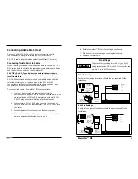
CAUTION: The rubber feet MUST BE INSTALLED if the PowerStar™
III is installed on a table-top or other flat surface. Failure to observe
this caution could cause the PowerStar™ III to overheat and could
result in data transmission failure and/or equipment damage.
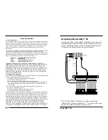
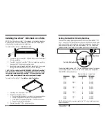
Setting Twisted Pair Polarity Switches
There are two sets of polarity switches at the 14-port
PowerStar™ III
front – one set for the left controller or host port and seven device ports
and one set for the right controller or host port and seven device ports –
and one set at the front of the 7-port PowerStar™ III. The A-B switch
settings reverse the polarity of the twisted pair connector active pins.
The factory default setting is "A". The following chart shows, for various
connector/pin options, the correct A-B switch setting and compatible
TRANSITION Networks baluns.
External Polarity Compatible
Connector
Pins
Switch Setting
TN Balun
RJ-11
3 & 4
A
3-1143
RJ-11
" B
3-1134
RJ-11
2 & 5
A
3-1152
RJ-11
" B
3-1125
RJ-45
1 & 2
A
3-4521
RJ-45
" B
3-4512
RJ-45
3 & 6
A
3-4563
RJ-45
" B
3-4536
RJ-45
4 & 5
A
3-4554
RJ-45
"
B
3-4545
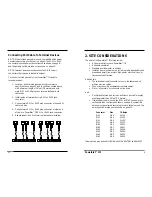
NOTE: Set the Link Ports polarity switch to “A” when installing twinax
cable to the host.
Ports 0-6
Link
Twinax
RJ-45
Main Link Input Select
Polarity Settings
Ports 0-6
Link
Twinax
RJ-45
Main Link Input Select
Polarity Settings
Ports 0-6
Link
Twinax
RJ-45
Main Link Input Select
Polarity Setting Switches