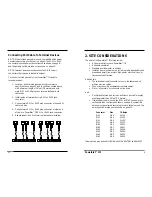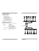
16
3
PowerStar™ III
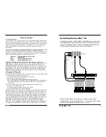
Powering the PowerStar™ III
To power ON the PowerStar™ III:
1. Locate the power receptacle on the back of the PowerStar™ III.
2. Connect the PowerStar™ III power connector end of the power
supply adapter to the PowerStar™ III.
3. Connect the external power connector end of the power
supply adapter to external AC power.
NOTE: After the power supply adapter is connected to the PowerStar™
III and to external power, the green Power LED is illuminated.
4. OPERATION
The PowerStar™ III normally requires no intervention beyond
occasionally monitoring the status LEDs.
5. MAINTENANCE
WARNING: DO NOT, UNDER ANY CIRCUMSTANCES, open
and attempt to repair the PowerStar™ III. Failure to observe
this warning could result in personal injury or death from
electrical shock.
NOTE: Failure to observe the above warning will immediately void the
warranty.
Technical Support Contact
For assistance in fault isolation and in maintaining the PowerStar™ III,
contact:
Technical Support
(800) 260-1312
or your local distributor.
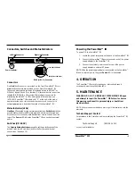
Connectors, Switches and Status Indicators
Connectors
One Link (host) connector is provided on the 7-port PowerStar™ III; two
Link (host) connectors are provided on the 14-port PowerStar™ III.
These connectors each provide an RJ twisted pair link to AS/400™ or
S/3x host signals. Seven (7) or fourteen (14) terminal device connectors,
labeled 0, 1, 2, 3, 4, 5, or 6, provide RJ twisted pair connection for
distributing the AS/400™ or S/3x host signals to terminal devices.
(AT BACK) PowerStar™ III models with “-T” at the end of the model
number provide one or two twinax host connectors. A connector to
external power also is located at the back of the PowerStar™ III.
Status Indicators (LEDs)
Line Sync (illuminated during normal operation) and Parity Error (blinks
at error) status indicators (LEDs) are provided next to each twisted pair
RJ connector for monitoring data transfer from host to link and from link
to port. The Power LED indicates PowerStar™ III connection to external
power.
Switches (ON BACK)
The Polarity Setting Switches are used to set the polarity sense of the
active RJ pins for the Link (host) and for the Port (terminal device)
connections. (See page 10.)
PowerStarIII
Link
0
1
2
3
4
5
6
Line Sync
Parity Error
Link
0
1
2
3
4
5
6
Line Sync
Parity Error
Power Indicator
Power
RJ-45 (or RJ-11) Connector
Line Sync Indicator
Parity Error Indicator
Left Link Connector
Right Link Connector
3

