


4
15
PowerStar™ III
2. SITE CONSIDERATIONS
The site for the PowerStar™ III must provide:
•
AC power outlet for each PowerStar™ III
•
Adequate ventilation
•
Standard environmental conditions
•
Isolation from electrical noise, including radio transmitters and
broadband amplifiers, motors, high power electrical lines, or
fluorescent light fixtures.
Additionally:
•
The twisted pair cables should not run in the same conduit
with power line cables,
•
Phone lines should be separated from data cables,
•
Flat or “silver satin” wires should not be used.
And:
•
Unshielded twisted pair, twinax, and fiber optic cable lengths
must be greater than 25 feet (7.6 meters),
•
If twisted pair cable is used, the RJ-11 or RJ-45 connector pin
settings must be configured as shown on page 8, compatible
baluns must be selected according to the chart below, and the
polarity switch must be set as shown on page 10.
Connector
Pins
TN Balun
RJ-11
3 & 4
3-1134
RJ-11
4 & 3
3-1143
RJ-11
2 & 5
3-1125*
RJ-11
5 & 2
3-1152
RJ-45
1 & 2
3-4512
RJ-45
2 & 1
3-4521
RJ-45
3 & 6
3-4536
RJ-45
6 & 3
3-4563
RJ-45
4 & 5
3-4545
RJ-45
5 & 4
3-4554
*Same active pins as used in IBM baluns P/Ns 69x7883 and 96x6187.
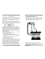
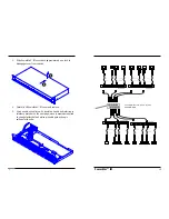
Connecting Port Cable to Terminal Devices
NOTE: When twisted pair cable is used, compatible baluns must
be selected according to the chart on page 4, the RJ-11 or RJ-45
connector pin settings must be configured as shown on page 8,
and the polarity switch must be set as shown on page 10.
NOTE: Terminal devices must be connected ONLY to port
connectors that carry an installed link signal.
To connect twisted pair cable from PowerStar™ III ports to
terminal devices:
1. Locate or build twisted pair cables that conform to
specifications on page 23 and to conditions noted above,
with minimum length of 25 feet (7.6 meters) and with
male RJ-11 or RJ-45 plug connectors installed at both
cable ends
2. Install balun at terminal device RJ-11 or RJ-45 jack
connector.
3. Connect male RJ-11 or RJ-45 plug connector at one end of
cable to balun.
4. Connect male RJ-11 or RJ-45 plug connector at other end
of cable to PowerStar™ III RJ-11 or RJ-45 jack connector.
5. Repeat steps 1-4 until all terminal devices are installed.


