5
PowerStar™ IV
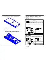
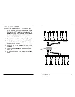
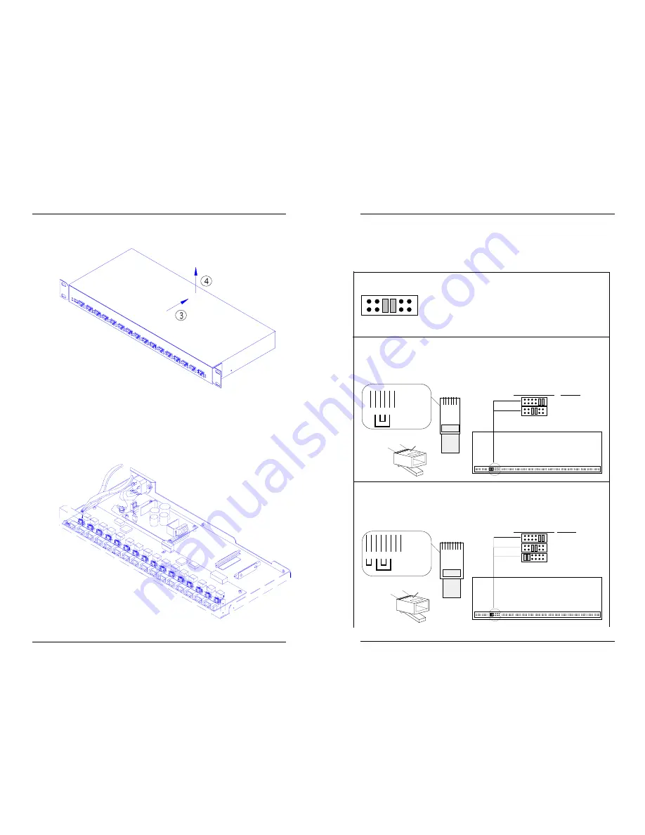
3. Slide PowerStar™ IV cover back approximately one inch to
disengage cover from chassis.
4. Carefully lift PowerStar™ IV cover and remove.
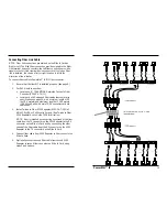
5. Using needle nose pliers with insulated handle and referring to
reference material on the next page, move jumpers as required
to change factory default active pin settings to active pin
settings for the site.
RJ-11 Pin Settings
Verify that the jumper locations activate the pins required for the
installation.
RJ-45 Pin Settings
Verify that the jumper locations activate the pins required for the
installation.
6. Rotate PowerStar™ IV cover to rest again on chassis.
7. Slide cover forward to engage cover against chassis.
8. Replace cover screws.
1
6
Top View
of the
RJ-11 Cable
Connector
1 2 3 4 5 6
Thick lines
indicate
pairs
Thin lines
indicate
pin leads
1
6
Crossview
of the RJ-11
Cable Connector
Top
2,5
3,4
1,6
PowerStar IV Jumpers
PowerStar IV Top Front
RJ-11 Pins
NOT USED
1 2 3 4 5 6 7 8
Top View
of the
RJ-45 Cable
Connector
Thick lines
indicate
pairs
Thin lines
indicate
pin leads
1
8
Crossview
of the RJ-45
Cable Connector
Top
3,6
4,5
1,2
7,8
PowerStar IV Jumpers RJ-45 Pins
NOT USED
1
8
PowerStar IV Top Front
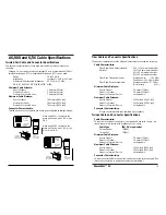
Pin Settings
The default factory setting for both RJ-11 and RJ-45
configurations is two centered jumpers. This default
setting activates pins 3 & 4 in the RJ-11 connector and
pins 4 & 5 in the RJ-45 connector.


