background image

6

PowerStar™ IV

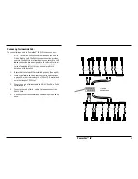
Optionally Installing Slide-In Cards

CAUTION: Wear a grounding device and observe electrostatic
discharge precautions when installing Slide-In Cards. Failure to
observe this caution could result in circuit board failure.

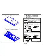
To install a Slide-In Card:

1. With the Slide-In Card components facing up, carefully guide

the Slide-In Card along the card guides until the Slide-In Card
connector meets the the PowerStar™ IV edge receptor.

2. Firmly push the card into the slot until the Slide-In Card

faceplate is flat against the PowerStar™ IV frame.

3. Rotate the two  Slide-In Card thumbscrews into the PowerStar™

IV threaded holes. 

Installing PowerStar™ IV in Rack or on Table

NOTE: The PowerStar™ IV is shipped with attached brackets for
standard 19-inch rack installation and with attachable feet for table-top
installation. Rackmount screws and clip nuts are NOT provided.

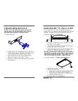
To install the PowerStar™ IV in 19-inch rack:

1. Locate four (4) screws (and clip nuts, if necessary) for each

PowerStar™ IV to be installed.

2. Carefully align the PowerStar™ IV between the 19-inch rack

mounting rails at the installation position.

3. Install two screws through right front bracket and two screws

through left front bracket, using clip nuts if necessary.

To install the PowerStar™ IV on table or other flat surface:

1. Carefully turn PowerStar™ IV to side.
2. Install four (4) rubber feet):

Remove protective paper from rubber foot adhesive surface.

Position rubber foot at bottom corner of repeater hub.

Press rubber foot against PowerStar™ IV surface to secure.

Repeat for remaining rubber feet.

3. Return PowerStar™ IV to upright position.

PowerStarIV

T R A N S I T I O N

0

1

2

3

4

5

6

0

1

2

3

4

5

6

Line Sync

Parity Error

Left Link

Right Link

Line Sync

Parity Error

CAUTION: The rubber feet MUST BE INSTALLED if the PowerStar™
IV is installed on a table-top or other flat surface. Failure to observe
this caution could cause the PowerStar™ IV to overheat and could
result in data transmission failure and/or equipment damage.

Summary of Contents for PowerStar IV

Page 1: ...us Indicators 3 2 SITE CONSIDERATIONS 3 3 INSTALLATION 4 Unpacking PowerStar IV 4 Setting Pin Jumpers 4 Optionally Installing Slide In Cards 6 Installing PowerStar IV in Rack or on Table 6 Setting Twisted Pair Polarity Switch 7 Powering the PowerStar IV 7 Connecting Link Cable to Host 8 Connecting Twisted Pair Link Cable 8 Connecting Twinax Link Cable 9 Connecting Fiber Link Cable 10 Connecting Po...

Page 2: ...ector at the front of the PowerStar IV or if one of the optional Slide In Cards SICs is installed through twinax or fiber connectors at the back of the PowerStar IV Twisted pair port connections are identified by PowerStar IV model number as either RJ 11 or RJ 45 connectors Separate transceiver circuitry isolates each port The following pin configurations are selectable RJ 11 pins 3 4 or 2 5 optio...

Page 3: ...S I T I O N 0 1 2 3 4 5 6 0 1 2 3 4 5 6 Line Sync Parity Error Left Link Right Link Power Indicator Line Sync Parity Error Power RJ 45 or RJ 11 Connector Line Sync Indicator Parity Error Indicator Left Link Connector Right Link Connector B A Polarity Setting Switches 2 SITE CONSIDERATIONS The site for the PowerStar IV must provide AC power outlet for each Powerstar IV Adequate ventilation Standard...

Page 4: ...onnector NOTE Since pin jumpers are located inside the PowerStar IV the PowerStar IV cover must be removed when setting the pin jumpers WARNING DISCONNECT POWER CORD from PowerStar IV before setting jumper pins Failure to observe this warning could result in personal injury or death from electrical shock WARNING AVOID CONTACT WITH POWER SUPPLY during jumper pin setting Failure to observe this warn...

Page 5: ...er to rest again on chassis 7 Slide cover forward to engage cover against chassis 8 Replace cover screws 1 6 Top View of the RJ 11 Cable Connector 1 2 3 4 5 6 Thick lines indicate pairs Thin lines indicate pin leads 1 6 Crossview of the RJ 11 Cable Connector Top 2 5 3 4 1 6 PowerStar IV Jumpers PowerStar IV Top Front RJ 11 Pins NOT USED 1 2 3 4 5 6 7 8 Top View of the RJ 45 Cable Connector Thick l...

Page 6: ...Star IV in 19 inch rack 1 Locate four 4 screws and clip nuts if necessary for each PowerStar IV to be installed 2 Carefully align the PowerStar IV between the 19 inch rack mounting rails at the installation position 3 Install two screws through right front bracket and two screws through left front bracket using clip nuts if necessary To install the PowerStar IV on table or other flat surface 1 Car...

Page 7: ...e Sync Parity Error Left Link Right Link Polarity Setting Switch Line Sync Parity Error B A Right Left Polarity Settings Ports Link Ports Link Powering the PowerStar IV To power ON the PowerStar IV 1 At PowerStar IV back locate the power receptacle and associated fuse NOTE Fuse must be installed at correct setting for power source voltage before connecting to AC outlet 2 Verify that fuse is instal...

Page 8: ... twisted pair cable is used compatible baluns must be selected according to the chart on page 4 the RJ 11 or RJ 45 connector pin settings must be configured as shown on page 8 and the polarity switch must be set as shown on page 18 To connect link cable to PowerStar IV link connectors 1 Locate or build twisted pair cables that conform to specifications on page 23 and to conditions noted above with...

Page 9: ...ors If only one twinax link is installed the choice of selecting left or right connection is left to the discretion of the installer 1 Be sure that the twinax SIC is installed properly See page 9 2 Locate or build twinax cables that conform to specifications on page 24 with minimum length of 25 feet 7 6 meters and maximum length of 5000 feet 3 Connect one end of twinax cable to AS 400 Sys 36 or 5x...

Page 10: ...ed fiber cables that conform to specifications on page 24 with minimum length of 25 feet 7 6 meters and maximum length of 3 000 meters 10 000 feet and with male TX RX connectors at both cable ends 3 Install Twinax to Fiber 5250 Repeater 5250 CV T F 11 at AS 400 Sys 36 or 5x94 controller port See Twinax to Fiber 5250 Repeater User s Guide 7336 for direction NOTE Fiber is installed by connecting one...

Page 11: ...alled at both cable ends 2 Install balun at terminal device RJ 11 or RJ 45 jack connector 3 Connect male RJ 11 or RJ 45 plug connector at one end of cable to balun 4 Connect male RJ 11 or RJ 45 plug connector at other end of cable to PowerStar IV RJ 11 or RJ 45 jack connector 5 Repeat steps 1 4 until all terminal devices are installed 4 OPERATION The PowerStar IV normally requires no intervention ...

Page 12: ...erates uses and can radiate radio frequency energy and if not installed and used in accordance with the instruction manual may cause harmful interference to radio communications Operation of this equipment in a residential area is likely to cause harmful interference in which case the user will be required to correct the interference at the user s own expense Canadian Regulations This digital appa...

Page 13: ...onnector Top 1 8 Fiber Cable and Connector Specifications The physical characteristics of the fiber cable must meet or exceed the following Cable Characteristics Fiber Optic Cable Recommended 62 5 125 µm multimode fiber Optional 100 140 µm multimode fiber 85 125 µm multimode fiber 50 125 µm multimode fiber Fiber Optic Transmitter Power Average power 15 0 dBm Peak power 12 0 dBm 1dBm Fiber Optic Re...

Reviews: