Transition Networks
SMxxTAT4Xx Install Guide
33785 Rev. B
Page
29
of
43
Connecting Powered Devices (PDs)
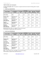
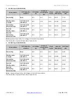
Note that this device does not comply with IEEE 802.3at at 48-51.4 VDC, or with IEE 802.3bt at 48-53.4 VDC.
The latest device label indicates:
•
802.3af: 48-57VDC
•
802.3at: 52-57VDC
•
802.3bt: 54-57VDC
This device drops ~1.3V from Vin to PSEout. IEEE requires PSEout voltages at the PSE output into the cable:
•
802.3af: 44VDC
•
802.3at: 50VDC
•
802.3bt: 52VDC
Not meeting this PSEout requirement may cause power up failures or power cycling with devices drawing the
maximum power with maximum cable loss.
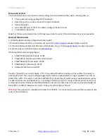
Power Connection
:
Warning
: Connect the power supply to the switch first, and then connect the power supply to
power. Otherwise catastrophic product failure may occur.
1.
Verify that power is off to the DC circuit that you are
going to attach to the switch PoE DC‐input connector. This can be either
of the two power supplies (AC‐input or
DC‐input) or site source DC.
2.
As an added precaution, place an appropriate safety flag and lockout device at the
source power circuit breaker, or place a piece of adhesive tape over the circuit breaker handle to prevent
accidental power restoration while you are working on the circuit.
Power Disconnection
: To disconnect power from the switch after a successfully boot:
1.
Turn off power to the
switch.
2.
Disconnect the cables.
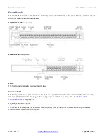
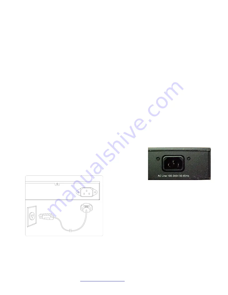
Connecting the AC Power Cord
1.
Connect the AC power cord to the AC power receptacle of switch.
2.
Connect the other end of the AC power cord to the AC power outlet.
3.
Check the SYS LED. If it is ON, the power connection is correct.

