Transition Networks
SMxxTAT4Xx Install Guide
33785 Rev. B
Page
32
of
43
Procedure
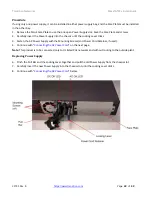
If using only one power supply, it can be installed in either power supply bay, and the Face Plate must be installed
in the other bay.
1.
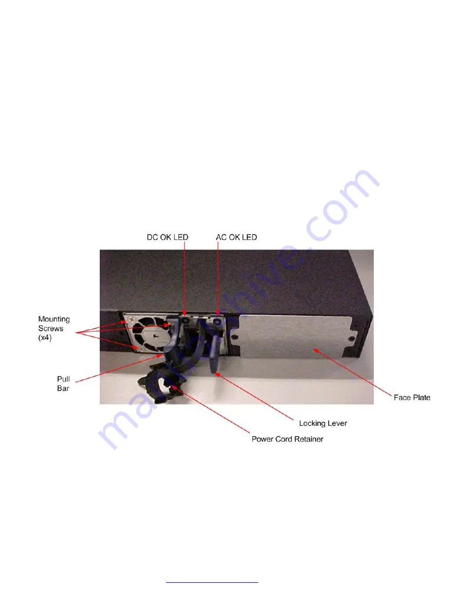
Remove the blank Face Plate to use the one open Power Supply slot. Save the Face Plate and screws.
2.
Carefully insert the Power Supply into the chassis until the Locking Lever clicks.
3.
Fasten the AC Power Supply with the Mounting Screws (and Power Cord Retainer, if used).
4.
Continue with “
Connecting the AC Power Cord
” on the next page.
Note
: This product is to be connected only to UL listed PoE networks and without routing to the outside plant.
Replacing Power Supply
6.
Pinch the Pull Bar and the Locking Lever together and pull the old Power Supply from the chassis slot.
7.
Carefully insert the new Power Supply into the chassis slot until the Locking Lever clicks.
8.
Continue with “
Connecting the AC Power Cord
” below.

