background image

P a g e

 | 


1.5 

 APPEARANCE AND DESCRIPTION 


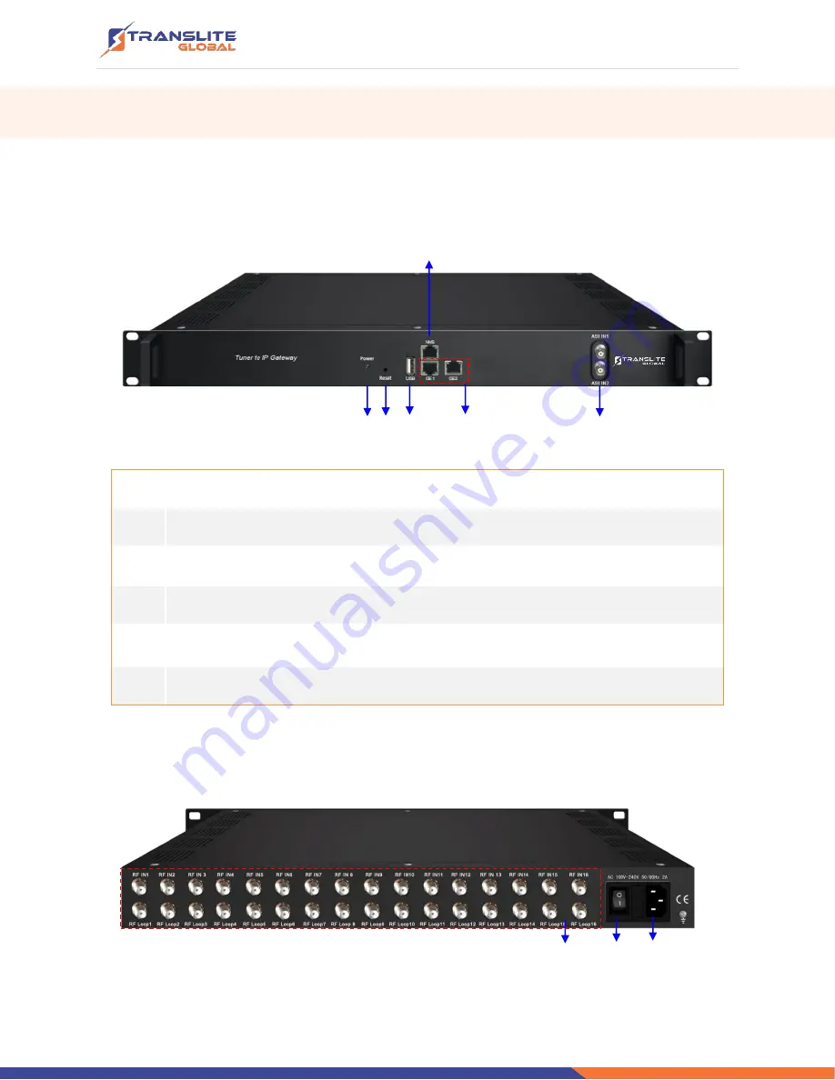
Front Panel 

Illustration 


         4


      1   2     3              5                                     6 


Power indicator 

Reset: Reset webmaster IP address, recover it to default IP address 

USB port for upgrade 

NMS port: Network management interface 

Data port

GE1&GE2

: IP out port 

ASI input port 


Rear Panel 

Illustration 


      1 

       2         3 

Summary of Contents for TL-9508B

Page 1: ...turing TRANSLITE GLOBAL LLC shall have no liability for any error or damage of any kind resulting from the use of this document COPY WARNING This document includes some confidential information Its usage is limited to the owners of the product that it is relevant to It cannot be copied modified or translated in another language without prior written authorization from TRANSLITE GLOBAL LLC PRODUCT ...

Page 2: ...LLATION GUIDE 8 2 1 ACQUISITION CHECK 8 2 2 INSTALLATION PREPARATION 8 2 3 DEVICE S INSTALLATION FLOW CHART ILLUSTRATED AS FOLLOWING 9 2 4 ENVIRONMENT REQUIREMENT 9 2 5 GROUNDING REQUIREMENT 10 2 5 1 FRAME GROUNDING 10 2 5 2 DEVICE GROUNDING 10 2 6 WIRE S CONNECTION 11 CHAPTER 3 WEB NMS OPERATION 11 3 1 LOGIN 12 CHAPTER 4 TROUBLESHOOTING 24 CHAPTER 5 PACKING LIST 25 CHAPTER 6 APPLICATIONS 25 ...

Page 3: ...P package then output the IP package through different IP address and ports BISS function is also embedded for tuner input to descramble your tuner input programs 1 2 KEY FEATURES Supports 16 FTA DVB S S2 S2X DVB C T T2 ISDB T ATSC optional input 2 ASI input Supports BISS descrambling Supports DisEqc function 16 MPTS or 512 SPTS output MPTS and SPTS output switchable 2 GE mirrored output IP addres...

Page 4: ...z 1000 MHz Constellation 16 32 64 128 256 QAM DVB T T2 Frequency In 30MHz 999 999 MHz Bandwidth 6 7 8 M bandwidth DVB S S2 Input Frequency 950 2150MHz Symbol rate DVB S QPSK 2 45Mbauds DVB S2 QPSK 1 45Mbauds 8PSK 2 30Mbauds Code rate 1 2 3 5 2 3 3 4 4 5 5 6 8 9 9 10 Constellation QPSK 8PSK DVB S Version 2 Frequency In 950 2150MHz Symbol rate 0 5 45Msps Signal Strength 65 25dBm FEC 1 2 2 3 3 4 5 6 ...

Page 5: ...8PSK 3 5 2 3 3 4 5 6 8 9 9 10 8APSK 5 9 L 26 45 L 16APSK 2 3 3 4 4 5 5 6 8 9 9 10 1 2 L 8 15 L 5 9 L 26 45 3 5 3 5 L 28 45 23 36 2 3 L 25 36 13 18 7 9 77 90 32APSK 3 4 4 5 5 6 8 9 9 10 2 3 L 32 45 11 15 7 9 Constellation QPSK 8PSK 8APSK 16APSK 32APSK Max input bitrate 125 Mbps ISDB T Input Frequency 30 1000MHz ATSC Input Frequency 54MHz 858MHz Bandwidth 6M bandwidth Output 512 SPTS IP mirrored out...

Page 6: ...1 Mode E Up to 850Mbps descramble individual program Miscellaneous Dimension 482mm 410mm 44mm W L H Approx weight 3 6kg Environment 0 45 work 20 80 Storage Power requirements 100 240VAC 50 60Hz Power consumption 20W 1 4 PRINCIPLE CHART ...

Page 7: ... Illustration 4 1 2 3 5 6 1 Power indicator 2 Reset Reset webmaster IP address recover it to default IP address 3 USB port for upgrade 4 NMS port Network management interface 5 Data port GE1 GE2 IP out port 6 ASI input port Rear Panel Illustration 1 2 3 ...

Page 8: ...hen users open the package of the device it is necessary to check items according to packing list Normally it should include the following items TL 9508B Tuner to IP Gateway User s Manual Grounding Cable RF In and Loop Out Cable Power Cord If any item is missing or mismatching with the list above please contact local dealer 2 2 INSTALLATION PREPARATION When you connect the power source make sure i...

Page 9: ...ivity of ground anti static material 1X10⁷ 1X10¹⁰ Grounding current limiting resistance 1M Floor bearing should be greater than 450Kg Environment Temperature 5 40 sustainable 0 45 short time installing air conditioning is recommended Relative Humidity 20 80 sustainable 10 90 short time Pressure 86 105KPa Door Window Installing rubber strip for sealing door gaps and dual level glasses for window Wa...

Page 10: ...grounding wire must be as thick and short as possible Users should make sure the 2 ends of grounding wire well electric conducted and be antirust It is prohibited to use any other device as part of grounding electric circuit The area of the conduction between grounding wire and device s frame should be no less than 25mm2 2 5 1 FRAME GROUNDING All the machine frames should be connected with protect...

Page 11: ...Connecting Grounding Wire When the device solely connected to protective ground it should adopt independent way say share the same ground with other devices When the device adopts united way the grounding resistance should be smaller than 1Ω Caution Before connecting power cord to TL 9508B Tuner to IP Gateway user should set the power switch to OFF CHAPTER 3 WEB NMS OPERATION User can only control...

Page 12: ...168 99 xxx xxx can be 0 to 255 except 252 to avoid IP conflict Use web browser to connect the device with PC by inputting this device s IP address in the browser s address bar and press Enter It displays the Login interface as Figure 1 Input the Username and Password Both the default Username and Password are admin and then click Login to start the device setting Figure 1 Summary Status When we co...

Page 13: ...lick Tuner Input it displays the interface where users can check the 16 Tuners input status TL 9508B supports multi tuners switch manually Figure 3 Figure 3 User can click any item here to enter the corresponding interface to check information or set the parameters System information Multi tuners input ...

Page 14: ...P a g e 14 Clicking Edit to set parameters for tuner DVB T2 DVB T DVB C J 83A C ...

Page 15: ... g e 15 DVB C J 83B ISDB T Parameter ASI input From the menu on top side of the webpage click ASI Input it displays the interface where users can check the 2 channels of ASI input status Figure 4 Figure 4 ...

Page 16: ...terface where users can set the output TS and configure TS ID and ON ID Figure 5 Figure 5 Parameter BISS From the menu on left side of the webpage clicking BISS it displays the interface where users can configure BISS and descramble the input channels Figure 6 Figure 6 ...

Page 17: ...nd Output Area with buttons in Operation Area Instructions are as below To filter not filter the source CA information To enable disable the PID remapping To refresh the input program information To refresh the output program information Select one input program first and click this button to transfer the selected program to the right box to output Similarly user can cancel the multiplexed program...

Page 18: ...cking program in output area it triggers a dialog box Figure 8 where users can input new information Figure 8 Note TL 9508B support 16 Tuner input and 2 ASI input with 512 SPTS output the parameter interface is different from MPTS When users switch SPTS to MPTS new mode will work after reboot the device Parameter BISS From the menu on left side of the webpage clicking BISS it displays the interfac...

Page 19: ...page clicking Program Parse it displays the interface where users can parse the program from the input channels When users disable the ASI input TL 9508B can support 16 Tuner input with 16 MPTS IP output Figure 10 Figure 10 Select the output carrier Enable and Disable the ASI input ...

Page 20: ... Tuner input and 2 ASI input with 16 MPTS IP output Figure 11 Figure 11 Parameter IP Stream TL 9508B supports TS to output in IP 16 MPTS format through the GE1 or GE2 port Clicking IP Stream it displays the interface where to set IP out parameters Figure 12 Figure 12 ...

Page 21: ...ace as Figure 13 where to set network parameters Figure 13 System Date Time Clicking Date Time it displays the interface as Figure 14 where to set date and time Figure 14 Set GE1 IP address Set NMS IP address the default IP address is 192 168 0 136 Set GE2 IP address ...

Page 22: ...ord it displays the screen as Figure 15 where to set the login account and password for the web NMS Figure 15 System Save Restore From the menu on left side of the webpage clicking Save Restore it displays the screen as Figure 16 where to save or restore your configurations Figure 16 ...

Page 23: ...s Figure 17 where to backup or load your configurations Figure 17 System Firmware From the menu on left side of the webpage clicking Firmware it displays the screen as Figure 18 where to update firmware for the device Figure 18 Select IP output Mode click Apply and reboot the device then the new mode can start to work ...

Page 24: ...l and other heat sink bores if necessary Checking the input AC within the power supply working range and the connection is correct before switching on device Checking the RF output level varies within tolerant range if it is necessary Checking all signal cables have been properly connected Frequently switching on off device is prohibited the interval between every switching on off must greater tha...

Page 25: ...P a g e 25 CHAPTER 5 PACKING LIST TL 9508B Tuner to IP gateway User s Manual Grounding Cable RFin and Loopout Cable Power Cord CHAPTER 6 APPLICATIONS ...

Page 26: ...P a g e 26 ...

Reviews: