background image

P a g e

 | 


DISCLAIMER


No part of this document may be reproduced in any form without the written permission of the copyright 

owner. 

The contents of this document are subject to revision without notice due to continued progress in 

methodology, design, and manufacturing. TRANSLITE GLOBAL LLC shall have no liability for any error or 

damage of any kind resulting from the use of this document. 


COPY WARNING


This document includes some confidential information. Its usage is limited to the owners of the 

product that it is relevant to. It cannot be copied, modified, or translated in another language 

without prior written authorization from TRANSLITE GLOBAL LLC 


PRODUCT MODEL NUMBER:


TL-9916 16 in 1 IP QAM 

MODULATOR 

ABOUT THIS 

MANUAL 


Summary of Contents for TL-9916

Page 1: ...ing TRANSLITE GLOBAL LLC shall have no liability for any error or damage of any kind resulting from the use of this document COPY WARNING This document includes some confidential information Its usage...

Page 2: ...IDE 7 2 1 ACQUISITION CHECK 7 2 2 INSTALLATION PREPARATION 8 2 3 DEVICE S INSTALLATION FLOW CHART ILLUSTRATED AS FOLLOWING 8 2 4 ENVIRONMENT REQUIREMENT 9 2 5 GROUNDING REQUIREMENT 9 2 5 1 FRAME GROUN...

Page 3: ...d low cost This is very adaptable to newly generation CATV broadcasting system 1 2 KEY FEATURES 3 GE ports max 512 IP in Data1 Data2 bi directional ports max 512 IP in 16 IP out Data port located on f...

Page 4: ...auto manually optional PCR accurate adjusting PSI SI table automatically generated Scrambling Parameters Max simulscrypt CA 4 Scramble Standard ETR289 ETSI 101 197 ETSI 103 197 Connection Local Remot...

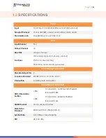
Page 5: ...s 75 impedance RF Range 50 960MHz 1kHz stepping Output Level 20dBm 10dBm 87 117db V 0 1dB stepping MER 40dB General Dimension 420mm 440mm 44 5mm WxLxH Temperature 0 45 operation 20 80 storage Power Su...

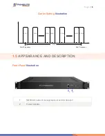
Page 6: ...ting Illustration CH 15 CH X3 CH X2 CH 16 CH X1 CH 1 192M Start Frequency End Frequency CH 2 1 5 APPEARANCE AND DESCRIPTION Front Panel Illustration 1 2 1 NMS CAS network management port and CA data p...

Page 7: ...R 2 INSTALLATION GUIDE This section is to explain the cautions the users must know in some case that possibly injure may bring to users when it s used or installed For this reason please read all deta...

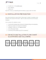
Page 8: ...also refer rear panel chart during the installation The main steps of the installation include Checking the possible device missing or damage during the transportation Preparing relevant environment f...

Page 9: ...e Pressure 86 105KPa Door Window Installing rubber strip for sealing door gaps and dual level glasses for window Wall It can be covered with wallpaper or brightness less paint Fire Protection Fire ala...

Page 10: ...oid circling The area of the conduction between grounding wire and grounding strip should be no less than 25mm2 2 5 2 DEVICE GROUNDING Connecting the device s grounding rod to frame s grounding pole w...

Page 11: ...PC Personal Computer and the device with a net cable and use ping command to confirm they are on the same network segment For instance the PC IP address is 192 168 99 252 we then change the device IP...

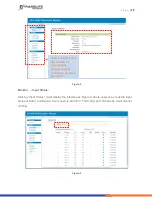
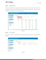
Page 12: ...y the interface as Figure 3 where users can check the input status of Data1 and Data 2 Users need to add IP in TS Config part Otherwise it will monitor nothing Figure 3 User can click any item here to...

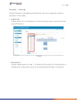
Page 13: ...users can check output status of the 16 carriers and 16 IPs Users need to enable the output status in Modulator and IP Stream part Otherwise it will monitor nothing Figure 4 Monitor AC Checked Clicki...

Page 14: ...ce Output TS X Clicking Output TS X it will display the interface as Figure 6 where users can select the output TS channels Figure 6 Stream Select Clicking Stream Select and click to add IP input then...

Page 15: ...uts channel To check input IP lock or not green means current IP locked To check current TS overflow or not red color means current TS overflow need reduce program Enable disable the CA Filter functio...

Page 16: ...e input programs To select all the output programs To parse programs time limitation of parsing input programs Program Modification The multiplexed program information can be modified by clicking the...

Page 17: ...ass it will display the interface as Figure 10 where user can add PIDs to be passed click the symbol input current IP channel number then input current IP source PID and output PID which is customer n...

Page 18: ...lator Clicking Modulator it will display the interface as Figure 12 where to set RF output parameters This field indicates the current outputting programs The programs selected will be scrambled Scram...

Page 19: ...ers can set all channels configration When users click Channel config button it triggers a dialog box as follow where users can set the corresponding channel configuration Click Channel config to set...

Page 20: ...hrough the DATA port Clicking IP Stream it will display the interface as Figure 13 where to set IP out parameters Figure 13 When users click Quickly Config button it triggers a dialog box where users...

Page 21: ...ing MPTS channel configuration System Network Clicking Network it will display the interface as Figure 14 where to set network parameters Figure 14 Click to enable the status and select TS out thru Da...

Page 22: ...splay the screen as Figure 15 where to set the login account and password for the web NMS Figure 15 System Configuration Clicking Configuration it will display the screen as Figure 16 where to set you...

Page 23: ...Firmware it will display the screen as Figure 17 where to update firmware for the device Figure 17 System Date Time Clicking Date Time it will display the interface as Figure 18 where users can set d...

Page 24: ...ITE products have been passed the testing and inspection before shipping out from the factory The testing and inspection scheme already covers all the Optical Electronic and Mechanical criteria which...

Page 25: ...it is necessary Checking all signal cables have been properly connected Frequently switching on off device is prohibited the interval between every switching on off must greater than 10 seconds Condi...

Page 26: ...P a g e 26 CHAPTER 6 APPLICATIONS...

Reviews: