Page
28
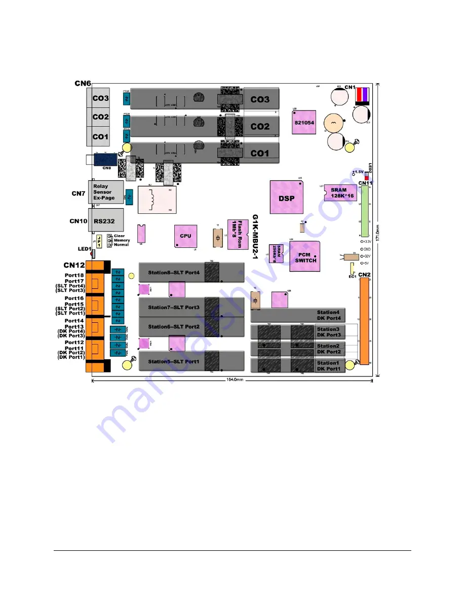
G1K-MBU2 Main Board Unit
1. CN1: Power connection to G1K-PWU CN3
2. LED2: DSP operation indication when slow flashing is normal
3. CN11: To G1K-NFC 128 CN1
4. EC1: Gold capacitor which provided for Real Time Clock
5. CN2: To G1K-TLU CN1
6. CN6: CO 1~CO 3 input from Central Office
7. CN8: External Music
8. CN7: Relay/Sensor/Ex-Page
9. CN10: RS232 connection
10. JP1: Clear Flash Memory / Normal Operation
11. LED1: System operation indication when slow flashing is normal
12. CN12: Connections for Digital Ports 11~14 (ST1~ST4) and SLT Ports 15~18 (ST5~ST8)
Summary of Contents for Lynx DK6 Series
Page 1: ...Telephone System Master Programming Manual Rev 2 1c ...
Page 2: ......
Page 24: ...Page 24 ...
Page 34: ...Page34 ...
Page 40: ...Page40 ...
Page 44: ...Page44 DK6 Key Telephone Key Layout 18 Button DK7 Key Telephone Key Layout ...


