background image

4.   Installation

(1) System Installation

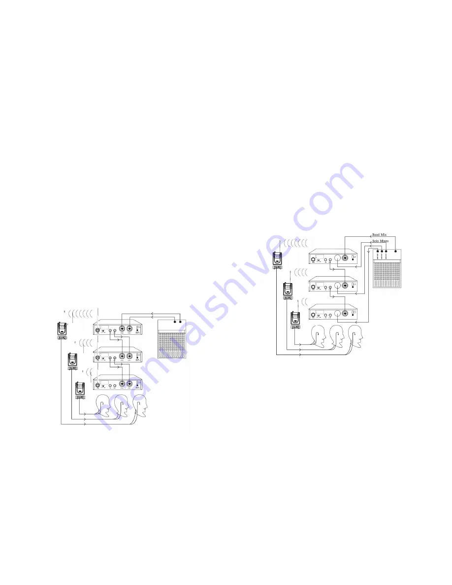
LOOP Applications

Use the Loop OUT L (left) and R (right) outputs to send a copy of the audio signal
going into the transmitter to other devices. Shown here are a few examples of the
many configurations for the LOOP outputs.

NOTE: The input level control and the input pad do not affect the level of

the LOOP signals.

Stereo for multiple Systems

Use the LOOP OUT connectors to send one stereo signal from the mixing console
to multiple IEM 4.16-RX wireless transmitters. This frees up outputs on the mixing 
console for other uses.

Connect the first transmitter to the mixer.
Connect the next transmitter to the first transmitter‘s LOOP outputs. Form 
a chain using all transmitters in your installation.

IEM S4.16-RX

IEM S4.16-RX

IEM S4.16-TX

IEM S4.16-TX

IEM S4.16-TX

6

7

Mix Mode for Multiple Systems

Some performers need to hear more of their own voice or instrument while others
want to hear more of the band. With this setup, each performer hears a 
combination of the whole band and their own instrument and the performer can
use the receivers balance control to create the desired mix of the whole band to
input 2 of the first transmitter. Connect input 2 of the next transmitter to the
LOOP OUT R output of the first transmitter. Continue the chain with all the 
transmitters. Next, create sole mixes for each performer using the auxiliary 
outputs of the mixing console. Send these mixes to input 1 of each performers
transmitter

IEM S4.16-RX

IEM S4.16-RX

IEM S4.16-RX

IEM S4.16-TX

IEM S4.16-TX

IEM S4.16-TX

IEM S4.16-RX

(2) Power Installation

Connect the output port of the DC12V-15V/800mA to the input of the DC
Power of the transmitter.

(3) Turn On Power

Press the power button and the LCD will illuminate, meanwhile more 
information will be displayed and will output the transmitting 
signal once the PLL circuitry is locked

Summary of Contents for IEM S4.16

Page 1: ... TOA Corporation UK Limited HQ3 Unit 2 Hook Rise South Surbiton Surrey KT6 7LD England Telephone 44 0 870 774 0987 Fax 44 0 870 777 0839 Email sales trantec co uk www trantec co uk IEM S4 16 Professional in ear Wireless Monitoring System ...

Page 2: ...train unwanted noise 2 Product Introduction The Trantec IEM S4 16 TX is a stereo UHF transmitter and in every 24 MHz there are 16 preset frequencies The main features are as follows a LCD Panel b Standard 19 2 metal mainframe c Balanced and unbalanced input jack d Optional stereo and mono channels e With PLL synthesized technology f With compressing and expanding circuitry S N is over 90dB g Built...

Page 3: ...teries x 2 IEM S4 16 1RX receiver x 1 Stereo headphones x 1 Waterproof bag x 1 1 3 7 6 2 1 5 4 2 4 Function Instructions 1 2 3 4 5 6 7 8 9 10 11 12 13 14 15 Front Panel Rear Panel 1 2 3 4 5 6 7 8 9 10 11 12 13 14 15 Power switch and power indicator Up Down Set Headphone output jack with stereo monitoring signal LCD Window of infrared data transmission Antenna connector High and Low RF switch Left ...

Page 4: ...indow UP DOWN SET Optional switch stereo and mono channels Low power indicator RF signal indicator Battery cover 4 3 Battery Installation 1 Put the power switch to OFF and press the open side of the battery cover and slide to open cover 2 Place two pieces of AA batteries 1 5V with the correct polarity 3 Close the battery cover 4 Switch power to ON and the LCD will display showing that the CPU rece...

Page 5: ...tems Some performers need to hear more of their own voice or instrument while others want to hear more of the band With this setup each performer hears a combination of the whole band and their own instrument and the performer can use the receivers balance control to create the desired mix of the whole band to input 2 of the first transmitter Connect input 2 of the next transmitter to the LOOP OUT ...

Page 6: ...ally according to the frequency or channel b Press UP and DOWN button to the desired frequency or channel you re quire The frequency or chanel you have chosen will begin to flash c Press SET button and the frequency or channel has been fixed and the CPU will lock the frequency the LCD will stop flashing and will revert to it s orignal status Select Frequency Panell Changing Frequency Save Frequency 7...

Page 7: ...e LCD will display DISP NAME to show name e Press SET to confirm your choice a c b d 11 Name Configuration a Press SET to scroll through the options until the unit displays RENAME then press SET to confirm b Press DOWN and AAA will be displayed press DOWN to set letters or numbers c Press SET to move to the last setting of character and repeat the operation of b and c to finish the setting of 8 charac...

Page 8: ...press b Press SET to confirm and will be displayed Press again to display frequency c Press to show and press SET to display channel a c b 17 Setting the Lock Function a Press SETand press to show b Press SET to confirm and LCD will display meaning the lock function has been relieved to release c Press to show and press SET the setting function has been locked a c b a c b 18 Configuration of Receiver...

Page 9: ...64 870 Band width 24MHz Oscillation PLL synthesized Channel separation interval 25KHz Frequency stability 0 005 0 C 50 C Modulation mode FM stereo Max deviation 68KHz Frequency response 80Hz 15KZ 3DB Stereo separation 45dB at 1KHz Output jack 3 5mm stereo headphone jack Power AA battery x 2 Battery life 8 hours under normal operating conditions Antenna Fixed 1 2 Dimensions 88 L x 65 W x 32 H Weigh...

Reviews: