Chapter 2: Connecting to the ER-1000
TR0190 Rev. B1
13
2
Connecting to the EL-500
The EL-500 can be configured and monitored by connecting to one of its network interfaces.
The wired Ethernet interface on the EL-500 should be used for initial configuration of the
device, but the wireless network interface can be used to connect to the device after initial
configuration has been completed.
2.1
Network Interfaces
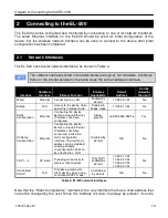
The EL-500 has several network interfaces, as shown in Table 4.
The network interfaces listed in the table below are logical, not hardware, interfaces.
Some of the interfaces listed in the table share the same hardware interface.
Interface
Hardware
Interface
Primary Function
Interface
Availability
Default
Address
Can be
altered by
the user?
Wired
Ethernet
Connecting to a LAN
Enabled by
default
10.253.0.1/24
No
Bridge
N/A
Access to the device when
operating in bridge mode
Enabled in
bridge mode
10.253.1.1/24
No
Static
Configuration
Ethernet
Configuring the device
before a unique Ethernet
IP address has been
configured
Always
present
169.254.253.253/16
Yes
OnRamp
Configuration
Ethernet
Configuring the device
before a unique Ethernet
IP address has been
configured. Unlike the
static configuration
interface, this interface’s
address can be modified,
allowing multiple
unconfigured EL-500s to
be attached to a LAN
Disabled by
default
N/A
No
VAP 1 – 4
AP radio
Providing connectivity to
wireless client devices
Only VAP1
enabled by
default
10.253.1.1/24
10.253.2.1/24
10.253.3.1/24
10.253.4.1/24
No
Centralized
DHCP
N/A
Provides a gateway for
client devices when using
centralized DHCP mode
All disabled
by default
N/A
No
Table 4. EL-500 network interfaces
Note that the “Static Configuration” interface is the only interface that has a fixed address that
cannot be changed by the user. Since this interface is known to always be present, it can be
Summary of Contents for EL-500
Page 20: ...Chapter 3 Using the Web Interface TR0190 Rev B1 20 Figure 8 Rebooting the EL 500...
Page 68: ...Chapter 11 Ethernet Interface Configuration TR0190 Rev B1 68 Figure 38 Wired DHCP settings...
Page 108: ...Chapter 16 Controlling Access to the ER 1000 TR0190 Rev B1 108 Figure 50 VAP ACL configuration...

