Chapter 10: Client Addressing Schemes
TR0190 Rev. B1
62
•
Each active client access interface must be assigned an address segment.
•
The IP address range start address (‘ip.implicit.start.requested’ in the CLI) must be one of
the following values: 1, 33, 65, 97, 129, 161, 193, 225.
•
The IP address range size (‘ip.implicit.size.requested’ in the CLI) must be one of the
following values: 31, 63, 127, 255.
•
The IP address range size and start address must be chosen such that the address
segment does not cross a netmask boundary. Table 8 lists allowed combinations.
•
The address spaces for enabled interfaces must start at different addresses.
•
The address spaces for enabled interfaces should not overlap.
Address range start
(ip.implicit.start.requested)
IP address range size (ip.implicit.size.requested)
31
63
127
255
1
Yes
Yes
Yes
Yes
33
Yes
No
No
No
65
Yes
Yes
No
No
97
Yes
No
No
No
129
Yes
Yes
Yes
No
161
Yes
No
No
No
193
Yes
Yes
No
No
225
Yes
No
No
No
Table 8. Allowed address segment start address and size combinations
Each of the enabled interfaces’ address segments should be configured to avoid overlap with
the other interfaces’ address segments. In the case where an EL-500 is not configured such
that this requirement is met, address spaces will be automatically reduced in size to prevent
overlap.
CLI
The start and size of client address spaces are set with the ‘ip.implicit.start.requested’ and
‘ip.implicit.size.requested’ parameters in the ‘wlan1’, ‘wlan2’, ‘wlan3’, and ‘wlan4’ interfaces.
Refer to Table 8 for allowed values for these parameters.
In the first example below, the ‘wlan1’ interface is set to use the entire class C address space
(this requires that all the other client access interfaces, wlan2-4, are disabled). In the second
example, the ‘wlan1’ interface is set to use the upper half of the class C address space.
>
use wlan1
eth0>
set ip.implicit.start.requested=1
eth0>
set ip.implicit.size.requested=255
>
use wlan1
eth0>
set ip.implicit.start.requested=129
eth0>
set ip.implicit.size.requested=127
Summary of Contents for EL-500
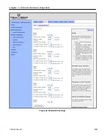
Page 20: ...Chapter 3 Using the Web Interface TR0190 Rev B1 20 Figure 8 Rebooting the EL 500...
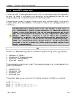
Page 68: ...Chapter 11 Ethernet Interface Configuration TR0190 Rev B1 68 Figure 38 Wired DHCP settings...
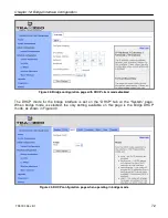
Page 108: ...Chapter 16 Controlling Access to the ER 1000 TR0190 Rev B1 108 Figure 50 VAP ACL configuration...

