Chapter 14: Client DHCP Configuration
TR0190 Rev. B1
89
14 Client DHCP Configuration
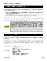
When operating in routed mode, two configuration options exist for assigning IP addresses to
client devices using DHCP:
•
The EL-500 hosts a local DHCP server and supplies IP addresses to devices attaching to
any of the client access interfaces
•
A centralized DHCP server supplies IP addresses to client devices, with the EL-500s
relaying DHCP messages between client devices and the centralized server.
The DHCP modes for client access interfaces on an EL-500 can be set individually to use a
local server, a centralized server, or be disabled. This allows a device to support client access
interfaces with a combination of centralized and localized DHCP.
An EL-500 operating in bridge mode can provide access to a DHCP server on
the LAN that it is bridging to, but it will not provide any local DHCP
functionality for client devices when operating in this mode. Centralized
DHCP server mode does not need to be configured in bridge mode since the
relaying occurs implicitly by virtue of the bridging function that the EL-500
provides.
It is possible to configure the bridge interface to receive an address via DHCP
(see section 12.1)
14.1 Using Local DHCP Servers
The EL-500 can be set to serve IP addresses to client devices on enabled VAP interfaces
using DHCP.
The IP addresses provided by the local DHCP server will be in the subnet defined by the LAN
prefix and node ID and the IP address range start address and size parameters in the
appropriate client access interface. For example, for the ‘wlan1’ interface, the start and end of
the address range are:
Start address =
<LAN prefix octet 1>.
< LAN prefix octet 2>.
<Node ID>.
<wlan1 IP address range start address> + 1
End address =
< LAN prefix octet 1>.
< LAN prefix octet 2>.
<Node ID>.
< wlan1 IP address range start address > -
< wlan1 IP address range size > - 2
BRIDGE
Summary of Contents for EL-500
Page 20: ...Chapter 3 Using the Web Interface TR0190 Rev B1 20 Figure 8 Rebooting the EL 500...
Page 68: ...Chapter 11 Ethernet Interface Configuration TR0190 Rev B1 68 Figure 38 Wired DHCP settings...
Page 108: ...Chapter 16 Controlling Access to the ER 1000 TR0190 Rev B1 108 Figure 50 VAP ACL configuration...

