background image


FCC Information 

This equipment has been tested and found to comply with the limits for a Class B digital device pursuant to 
part 15 of the FCC Rules. These limits are designed to provide reasonable protection against harmful 
interference when the equipment is operated in a Residential environment.  This equipment generates, uses, 
and can radiate radio frequency energy and, if not installed and used in accordance with the instruction 
manual, may cause harmful interference to radio communication. 
 
Operation in the 4940-4990 MHz band is restricted to the U.S. Operation in this range is restricted to the Public 
safety bands.  Use of these bands is restricted to entities that meet the requirements listed  the FCC Part 90.20 
Public Safety Pool and are properly licensed to operate a transmitter in the Public Safety band in accordance 
with Part 90Y of the technical rules can operate in the 4940-4990 MHz band. FCC regulations state in Part 90, 
operation in the 4.9-GHz band requires frequency coordination before the system can be operated.  
 
Operation of this equipment in residential area is likely to cause harmful interference in which case the user will 
be required to correct the interference at his or her own expense. 
 
The user should not modify or change this equipment without written approval from Tranzeo Wireless. 
Modification could void authority to use this equipment. 
 
For the safety reasons, people should not work in a situation which RF Exposure limits be exceeded. To 
prevent the situation happening, people who work with the antenna should be aware of the following rules  

1.  Install the antenna in a location where a distance of 65 cm from the antenna may be maintained. 
2.  While installing the antenna, do not turn on power to the unit. 
3.  Do not connect the antenna while the device is in operation. 
4.  The antenna used for this transmitter must not be co-located or operating in conjunction with any other 

antenna or transmitter. 


Safety Notices 

Safety Precautions: 

YOU MUST READ AND UNDERSTAND THE FOLLOWING SAFETY INSTRUCTIONS BEFORE 
INSTALLING THE DEVICE: 

• 

This antenna’s grounding system must be installed according to Article 810-15, 810-20, 810-21 of the 
National Electric Code, ANSI/NFPA No. 70-1993. If you have any questions or doubts about your 
antenna grounding system, contact a local licensed electrician. 

• 

Never attach the Grounding Wire while the device is powered.   

• 

If the ground is to be attached to an existing electrical circuit, turn off the circuit before attaching the 
wire. 

• 

Use the Tranzeo POE only with approved Tranzeo models. 

• 

Never install Radio Equipment, surge suppressors, or lightning protection during a storm. 

A BRIEF WORD ON LIGHTNING PROTECTION 

The key to a Lightning Protection is providing a harmless route for lightning to reach ground.  The system 
should not be designed to attract lightning, nor can it repel lightning.  National, State and local codes are 
designed to protect life, limb and property, and must always be obeyed.   

When in doubt, consult contact an electrician or professional trained in the design of 
grounding systems

.


Summary of Contents for TR-49

Page 1: ...QUICK START GUIDE FOR THE TRANZEO WIRELESS TR 49 REVISION 2 0a JANUARY 2ND 2006...

Page 2: ...situation which RF Exposure limits be exceeded To prevent the situation happening people who work with the antenna should be aware of the following rules 1 Install the antenna in a location where a di...

Page 3: ...TR AP Quick Start Guide Hardware Installation Product Kit Before installation make sure that you have the following items The TR 49 x 1 DC Power Adapter x 1 Power over Ethernet Adapter x 1 Ethernet B...

Page 4: ...ged Label Color Indicators POWER Red On Powered On Off No Power LAN Green On Ethernet Link Flashing Ethernet Traffic Off No Ethernet Link Radio Amber On Radio Link Flashing Radio Activity Off No Radio...

Page 5: ...of the Access Point Obstructions may impede performance of the unit Tools Required to Install One 3 8 wrench One 3 4 wrench One RJ 45 crimper A suitable length of Cat 5 cable to bring the signal from...

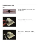
Page 6: ...Ethernet Boot Cover over the end of your Cat 5 cable Attach Ethernet Cable Lock on side of the Ethernet Boot This is easiest to do before you attach the RJ 45 Jack Tighten using a wrench or socket Tig...

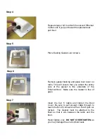
Page 7: ...able through to reach the RJ 45 connector with an RJ 45 jack at tached The Gasket must be attached to the Boot so that it sits between the radio and the boot Hand tighten only DO NOT OVERTIGHTEN as yo...

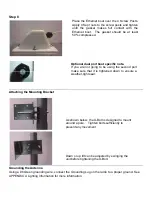
Page 8: ...e screw posts and tighten until the gasket makes full contact with the Ethernet boot The gasket should be at least 50 compressed As shown below the U Bolt is designed to mount around a pole Tighten bo...

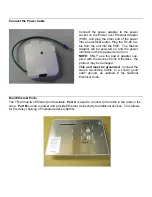
Page 9: ...er adapter to the power socket on the Power over Ethernet Adaptor POE and plug the other end of the power into an electrical outlet Plug the RJ 45 Ca ble from the unit into the POE The Station Adaptor...

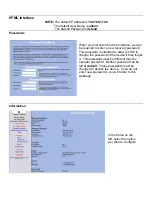
Page 10: ...nter a new recovery password This password is intended to allow the ISP to change the password of the device if they forget it This password must be different than the operator password Neither passwo...

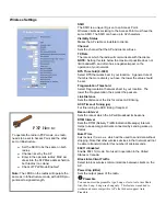
Page 11: ...Interval Sets the DTIM Delivery Traffic Indication Message Interval Helps to keep marginal clients connected by sending wake up frames Burst Time Sets the Burst Time in ms which will be used to send...

Page 12: ...ation is only displayed with Tranzeo Wireless Technologies Access Points Signal Status LEDs Un select to turn off the LEDs on the unit SMNP Parameters Here you set the Read Community string and Contac...

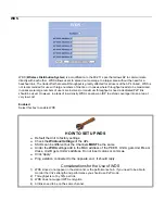
Page 13: ...w an ISP to extend coverage into an area at very low cost Enabled Select this box to enable WDS HOW TO SET UP WDS Default the Unit to factory settings Check the Wireless Settings of the APs SSIDs can...

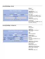
Page 14: ...y Activate Keys Enter your WEP keys NOTE Keys must be entered in HEX only Enabled Turn On WPA Cipher Type Select the Level of Encryption TKIP or AES PSK Enter your password Update Interval Enter the u...

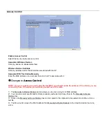
Page 15: ...ss Control NOTE If you are working via a radio link the first MAC you should add is the address of the station you are connecting from Otherwise you will lock yourself out of the radio 1 The Manually...

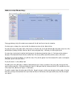
Page 16: ...written with the name on the client The third column is the IP address As with the name if the client supplies it via the Extended Info option it will appear Otherwise you can manually enter it The fo...

Page 17: ...en It shows the devices which have sent either a broadcast or directly tried to communicate with the device Under normal circumstances there should be a limited number of entries in this table especia...

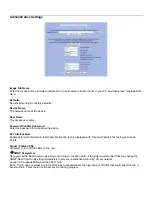
Page 18: ...h in line Network Configuration Router Mode You can choose Static DHCP or PPPoE Client IP configuration for the device Each of these options are explained on the following pages Note If you select DHC...

Page 19: ...DHCP pool Gateway Select This Unit to use the gate way set on the WAN interface of the radio or select Other to set a different gateway address DNS WAN Assigned Select to use the DNS server addresses...

Page 20: ...ion of the Destination IP signifies the network trying to be accessed and which part signifies the host that the packets will be routed to Note 255 255 255 255 is used to signify only the host that wa...

Page 21: ...er the higher it priority 0 is the highest priority and 255 in lowest Name The name here is for your reference only Protocol Enter the IP Protocol Number Common options are 0 for ANY 1 for ICMP 6 for...

Page 22: ...gement Port Forwarding This is a new feature It allows the radio to forward requests for certain ports to devices behind the router For example the customer has a webserver behind the Radio on a Priva...

Page 23: ...ients are on 192 168 1 0 24 then the source IP would be 192 168 1 1 to 192 168 1 254 4 Select Desintination IP Range Assuming that the entire outside world was to be blocked then 0 0 0 0 should entere...

Page 24: ...n in the Administrative Settings Window Receiving This box displays the current signal and the Lowest and Highest values For the most accurate readings data must be transmitted through the unit Transm...

Page 25: ...occur in the Unit s Processor LMAC or Lower MAC functions occur in the Radio Chipset You can click onto each speed level and see how the traffic breaks down In the TX statistics there should little t...

Page 26: ...sions are usually a sign that the radio and the device it is linked to are not on the same Duplex options One is at full while the other is at half Try locking both to the same values Collisions do no...

Page 27: ...he path of least impedance Coiling cables creates an air wound transformer which lowers the impedance This means you are in fact making your radios a more appealing target for surges What standard doe...

Page 28: ...a POE Radio Ground An ungrounded radio causes the surge to pass through the radio In this case the radio most likely will be damaged POE Antenna Radio Ground A grounded radio causes the surge to pass...

Page 29: ...not grounded the route for the surge is through the radio to the antenna and out through the building Mounting Pole Mounting Pole In this case the surge will be picked up by the Cat 5 cable and since...

Page 30: ...e cables 3 Test all grounds to ensure that you are using a proper Ground If using a electrical socket for Ground use a socket tester such as Radio Shack 22 141 4 Buy a copy of the National Electrical...

Page 31: ...OS enabled the voice quality remains consistently high with an MOS of 4 4 and maintains that level even with multiple FTP streams Automatic Traffic Classification Tranzeo Wireless Technologies softwar...

Page 32: ...he Internet connection and dynamically adjusting the way individual streams are handled at any point in time This enables latency sensitive traffic such as voice games or even web page requests to be...

Page 33: ......

Page 34: ...3 SWIPE IP with Encryption 54 NARP NBMA Address Resolution 55 MOBILE IP Mobility Decimal Keyword Protocol 56 TLSP Transport Layer Security using Kryptonet key management 57 SKIP SKIP 58 IPv6 ICMP ICMP...

Page 35: ...File System SIP 5060 5061 SIP 108 IPComp IP Payload Compression 109 SNP Sitara Networks Protocol 110 Compaq Peer Compaq Peer Protocol 112 VRRP Virtual Router Redundancy 113 PGM PGM Reliable Transport...

Reviews: