background image

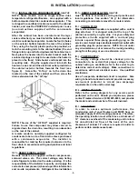
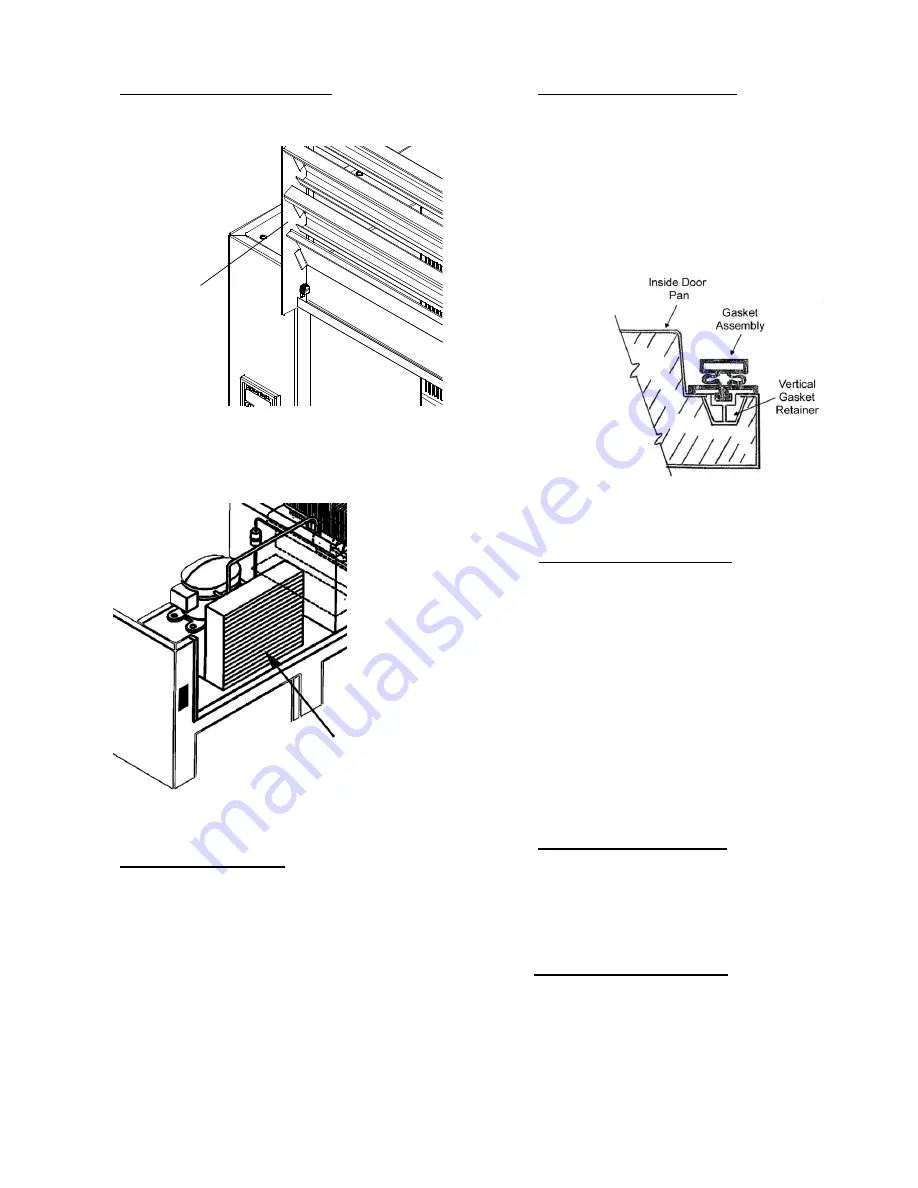
V. c - REPLACING THE GASKETS:
To remove the gasket to be replaced, grasp it firmly by
one corner and pull it out.  Before attempting to install a
new gasket, both the unit and the gasket itself must be
at room temperature.  Insert the four corners first by
using a rubber mallet (or hammer with a block of wood).
After the corners are properly inserted, work your way
towards the center from both ends by gently hitting with
a mallet until the gasket is completely seated in place
(see figure 11 for proper gasket placement).

NOTE: The gasket may appear too large, but if it is
installed as indicated above it will slip into place.

V. d - CLEANING THE EXTERIOR:
Exterior stainless steel should be cleaned with warm
water, mild soap and a soft cloth.  Apply with a
dampened cloth and wipe in the direction of the metal
grain.
Avoid the use of strong detergents and gritty, abrasive
cleaners as they may tend to mar and scratch the
surface.  Do NOT use cleansers containing chlorine, this
may promote corrosion of the stainless steel.
Care should also be taken to avoid splashing the unit
with water, containing chlorinated cleansers, when
mopping the floor around the unit.
For stubborn odor spills, use baking soda and water
(mixed to a 1 TBSP baking soda to 1 pint water ratio).

V. e - CLEANING THE INTERIOR:
For cleaning both stainless steel and anodized
aluminum interiors, the use of baking soda as described
in section 

V. d” is recommended.  Use on breaker strips

as well as door gaskets.  All interior fittings are
removable without tools to facilitate cleaning.

V. f - ADJUSTING THE SHELVES:
For shelves mounted on pins, first select the desired
location and remove the white plastic covers in the
interior back and sides by rotating them counter-
clockwise.  Remove the shelf pins by rotating them
counter- clockwise.  Install the pins in the desired
location by rotating clockwise.  Make sure the pin is
securely tightened down.  Do not over tighten.  Slide the
shelf into its new position, and replace the white plastic
covers into the holes vacated by the shelf pins.

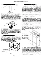
Fig. 7

Lift-Up Louver

Assembly

V. a - CLEANING THE CONDENSER:
Once the screws are removed, the panel can be pivoted
upwards allowing full access to the front facing
condenser (see figure 9).

Vacuum or brush any dirt, lint or dust from the finned
condenser coil, the compressor and other cooling
system parts (see figure 10).  If significant dirt is
clogging the condenser fins, use compressed air to
blow this clear.

Lower louver assembly and replace the screws to hold
it in place.

V. b - HINGE REPLACEMENT:
Both the door and hinge can be easily removed from the
cabinet.  To remove the door, remove the plug at the
bottom of the top hinge.  Inside the hinge there is a small
screw which secures the door in place.  Remove this
with a flat head screwdriver and the door can then be
lifted off the hinge.  To remove the door portion of the
hinge from the door, lift off the hinge cover and then
remove the three Phillips head screws which secure the
hinge in place on the door.  To remove the cabinet
portion of the hinge, remove the three Phillips head
screws which hold it in place.  On solid door units, the
top hinge(s) contains a microswitch for controlling the
interior lighting.
To reassemble the hinge reverse the previous procedure.

-6-

V. CARE & MAINTENANCE

 (cont

d)

Fig. 10

Condenser

Surface

Fig. 11

Summary of Contents for R & A Series

Page 1: ...ed to the unit Should you need service however call us on our toll free number 800 825 8220 between 7 30 am and 4 30 pm CST Monday thru Friday It is our pleasure to help and assist you in every possib...

Page 2: ...sting Thermostat Set Point Low Page 13 j Changing The Temperature Scale Page 13 k Setting The 24 Hour Clock Page 14 l Setting The Date Page 15 m Setting Daylight Savings Time Page 15 n Starting A Manu...

Page 3: ...own on its front side or back However if you must please be certain to allow the unit to remain in an upright position afterwards for 24 hours before plugging it in so that the compressor oils and ref...

Page 4: ...breaker strip near the bottom door opening Next loosen the thumb screws located along the floor at the threshold Place the ramp s on top of the loosened thumb screws and secure tabs on each end to br...

Page 5: ...nits serial tag It is the responsibility of the installer to specify and supply the correct size compressor s based upon this information and on site requirements Refrigerant line installation III INS...

Page 6: ...ontrols function upon termination of a defrost cycle is two fold First to prevent blowing warm air into the food storage area Second to prevent any condensation on the defrost coil from being blown in...

Page 7: ...SHELVES For shelves mounted on pins first select the desired location and remove the white plastic covers in the interior back and sides by rotating them counter clockwise Remove the shelf pins by ro...

Page 8: ...please check the following Is the electrical cord plugged in Is the fuse OK or circuit breaker on Is the power switch ON If after checking the above items and the unit is still not operating properly...

Page 9: ...refrigerator and freezer models only Note The 24 hour clock and the date must be set for the above information to be recorded at the correct time and date 6 Communication Ability An RS485 port port i...

Page 10: ...t lockouts or are retrieving the information from the data storage memory See Setting The 24 Hour Clock page 12 and Setting the Date page 15 Door Open The door open icon on the face of the control wil...

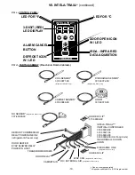
Page 11: ...HORN 337 60069 00 337 60070 00 HOLDER CLIP 377 60038 00 INTELA TRAUL VERTICAL CONTROLLER 337 60090 00 337 60091 00 337 60092 00 337 60098 00 Hot Food Units INCLUDES ALL SHOWN HORN DISCHARGE LINE HOLD...

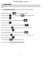
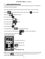
Page 12: ...security code 0 A 1 and the following instructions Press the set button The display will read Customer Service Access Press the set button The display will show three zeros with the left zero flashing...

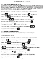
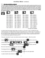
Page 13: ...ature range Typically freezers will range from 3 F to 0 F 19 C to 18 C and refrigerators will range from 36 F to 40 F 2 C to 4 C for this parameter setting This parameter is preset at the factory and...

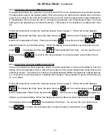
Page 14: ...re to your desired setting When the display shows the temperature you want press the set button The display will then read Thermostat Set Point High You can use the up or down arrow keys to scroll to...

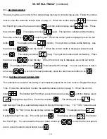
Page 15: ...5 00 a m H11 11 00 a m H17 5 00 p m H23 11 00 p m H06 6 00 a m H12 12 00 p m H18 6 00 p m H24 12 00 a m Follow the instructions to enter the customer access code on page 11 When the control displays T...

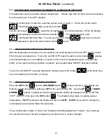
Page 16: ...y is displayed press the set button The display will then read Thermostat Set Point High You can use the up or down arrow keys to scroll to the next parameter press the alarm cancel button to exit VII...

Page 17: ...he set button The display will then read Thermostat Set Point High You can use the up or down arrow keys to scroll to the next parameter or press the alarm cancel button to exit The defrost icon will...

Page 18: ...00 a m 120 12 00 p m 180 6 00 p m 240 12 00 a m 063 6 30 a m 123 12 30 p m 183 6 30 p m 243 12 30 a m 070 7 00 a m 130 1 00 p m 190 7 00 p m 010 1 00 a m 073 7 30 a m 133 1 30 p m 193 7 30 p m 013 1 3...

Page 19: ...ay will then read Thermostat Set Point High You can use the up or down arrow keys to scroll to the next parameter or press the alarm cancel button to exit VII q ADJUSTING THE ROOM TEMPERATURE OFFSET T...

Page 20: ...arrow keys to scroll between for the 3 Second Audible Alarm Burst or for Continuous Audible Alarm When the display shows your choice of style press the set button The display will then read thermosta...

Page 21: ...please note that this feature is not available on versions of the control manufactured prior to September 2000 or if an alarm warning condition is present use the alternative ON OFF activation method...

Page 22: ...oor was kept open for a long period of time in both cases allow adequate time for the cabinet to recover its normal operating temperature c INTELA TRAUL setting too high readjust per instructions on p...

Page 23: ...Jewelers type door lock for sliding glass door model Hinge Cam 344 28488 00 Replacement hinge cam Hinge Cover 344 28486 00 Replacement hinge cover Hinge Spring Assist SER 29021 03 Alternative hinge s...

Page 24: ...of a Traulsen refrigeration product resulting in corrosion Avoid use of these on or around a Traulsen refrigeration product if at all possible 4 PROLONGED CONTACT WITH FOOD PRODUCT Many food products...

Page 25: ...when it first becomes visible When rust occurs do not allow it to remain for any period of time and remove it using the following method STEP ONE Use a lightly abrasive compound free of harmful chlori...

Page 26: ...ry any part of said control which proves to be defective Inspection by the TRAULSEN Service Department of parts claimed defective shall be final in determining warranty status The warranty is to inclu...

Page 27: ...ock 8 INTELA TRAUL 5 8 20 J K L Legs Installing The 2 3 Light Bulb Replacing The 7 Light Cover 7 Louver Assembly 5 6 M Manual Defrost Cycle 16 N O P Power Supply 4 R Remote Installation 3 Return Autho...

Page 28: ...lue Mound Road Fort Worth TX 76106 Phone 800 825 8220 Fax Svce 817 740 6757 Website www traulsen com HOURS OF OPERATION Monday thru Friday 7 30 am 4 30 pm CST Quality Refrigeration 2004 Traulsen All R...

Reviews: