20
VI. SERVICE PROCEDURES RBC50
VI.d
–
RBC50 EVAPORATOR ACCESS
(pre 2008)
1. Locate access panel at rear of left or right
power pack assembly.
2. Remove access panel
3. Remove evaporator housing cover
4. Reinstall in reverse order
VI.e
–
RBC50 EVAPORATOR ACCESS
(2008
–
Current)
1. Remove screws on the left and right side
holding the stainless steel work top in place
2. Use knife to score RTV seal around insulated
top.
3. Remove screws from top holding insulated top
in place
4. Remove insulated top.
5. Reinstall in reverse order.
VII. SERVICE PROCEDURES RBC100
VII.a
–
SENSORS AND PROBES
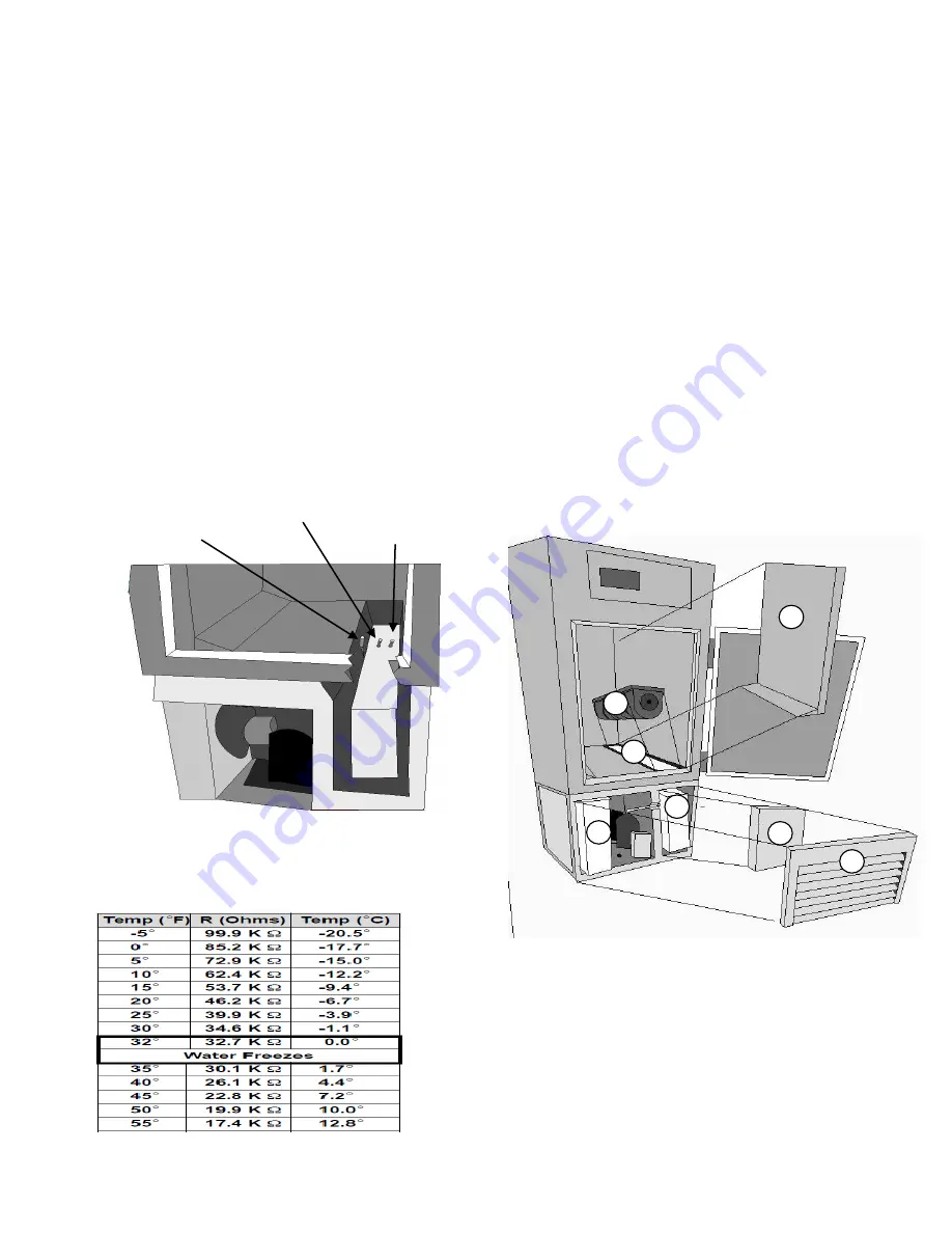
a.1 Air & Coil Sensor Locations RBC100
1. Air Sensor: Green
Mounted on return side of the evaporator coil
2. Maintenance Coil Sensor: Blue
Located in the top left of the evaporator coil
3. Blast Coil Sensor: Yellow
Located in the top right of the evaporator coil
a.2 Sensor and Probe Troubleshooting
All probes and sensors should return an Ohm
reading of 32.7K Ohms at 32F or 0C. Test by placing
the sensor or probe tip in ice with a little bit of water
and checking Ohm reading with an Ohm meter.
VII.b
–
ACCESS EVAPORATOR/REFRIG SYS
b.1 RBC100 Exploded View
1. Right side air duct/shelving
2. Blower assembly
3. Louver panel
4. Evaporator housing cover
5. Evaporator coil
6. Condensing unit
b.2 Accessing The Evaporator/Sensors
1. Remove the right side shelving and air duct
“1”
2.
Remove the blower assembly “2”
3. Access sensors in the evaporator coil
4. Reinstall in reverse order
b.3 Accessing The Evaporator/Defrost Heater &
Thermal Fuse
1.
Remove the louver panel assembly “3”
2.
Remove the evaporator housing cover “4”
3. Access defrost heater/thermal fuse
4. Reinstall in reverse order
CAB SENSOR(1)
BLAST COIL SENSOR(3)
MAINT COIL SENSOR(2)
1
2
3
4
5
5
6


