Page 10
FREESTANDING OPTIONAL EQUIPMENT (Continued)
5. Blower, Rear (Continued)
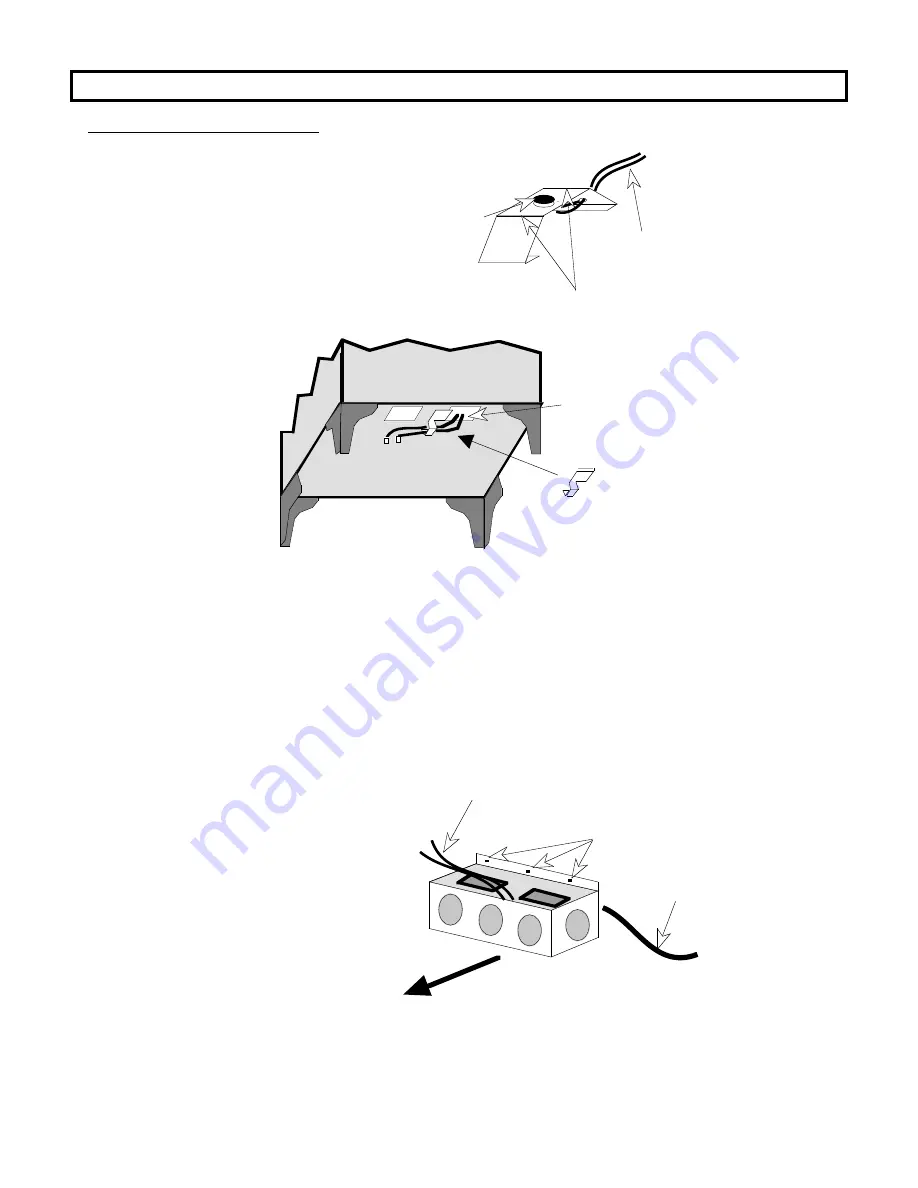
The thermodisk must come in contact
with the bottom of the firebox when it is
installed. To insure this, bend the metal
portion of the thermodisk assembly up or
down to create a snug fit.
Thermodisk
A s s e m b l y
Bend metal up or down here to create a snug fit
Wires that
attach to
blower box
Thermodisk
Slide the wire clip
over the edge of the
strip of metal
between the two
knock-outs removed
in step 1. Insert the
two thermodisk wires
into the eye of the
wire clip and pull the
slack wire out of the
stove.
Slide the wire clip over the
edge of the strip of metal
between the two knock-outs.
Feed the two thermodisk
wires into the eye of the
wire clip.
NOTE:
The wires coming from the thermodisk assembly must not have too much slack
Ð these wires pass near the firebox and can cause a short if the slack is not
taken in and held in place with the wire clip. Do not pull so hard on the wires
that you dislodge the thermodisk housing from its location.
There are two yellow wires coming out of the blower box. These two wires must exit the blower box
from the top, not through the small access hole in the back. Re-route these wires so they exit out of
the top of the blower box. Attach these two wires to the two wires coming from the thermodisk by
connecting the mating quick-connects. It does not matter which wire from the blower box connects to
which wire from the thermodisk assembly. Push all of the excess wire into the cavity inside the blower
box.
3.
Place the blower box near the bottom
rear of the stove and push any slack
wire into the blower box so that when
the blower box is attached the excess
wire will not contact the stove.
4.
Attach the blower box to the bottom
rear of the stove with the three screws
provided. Push the blower box up
against the stove while tightening the
screws.
The two yellow wires
attach to the thermodisk.
Three holes for attaching the blower
box to the back of the stove
Power Cord
(exits from back
of blower box)
FRONT


