background image

20

 Installation 

(qualified installers only)


© Travis Industries, Inc. 

4/11/22 - 1538 

Outdoor Linear Burners


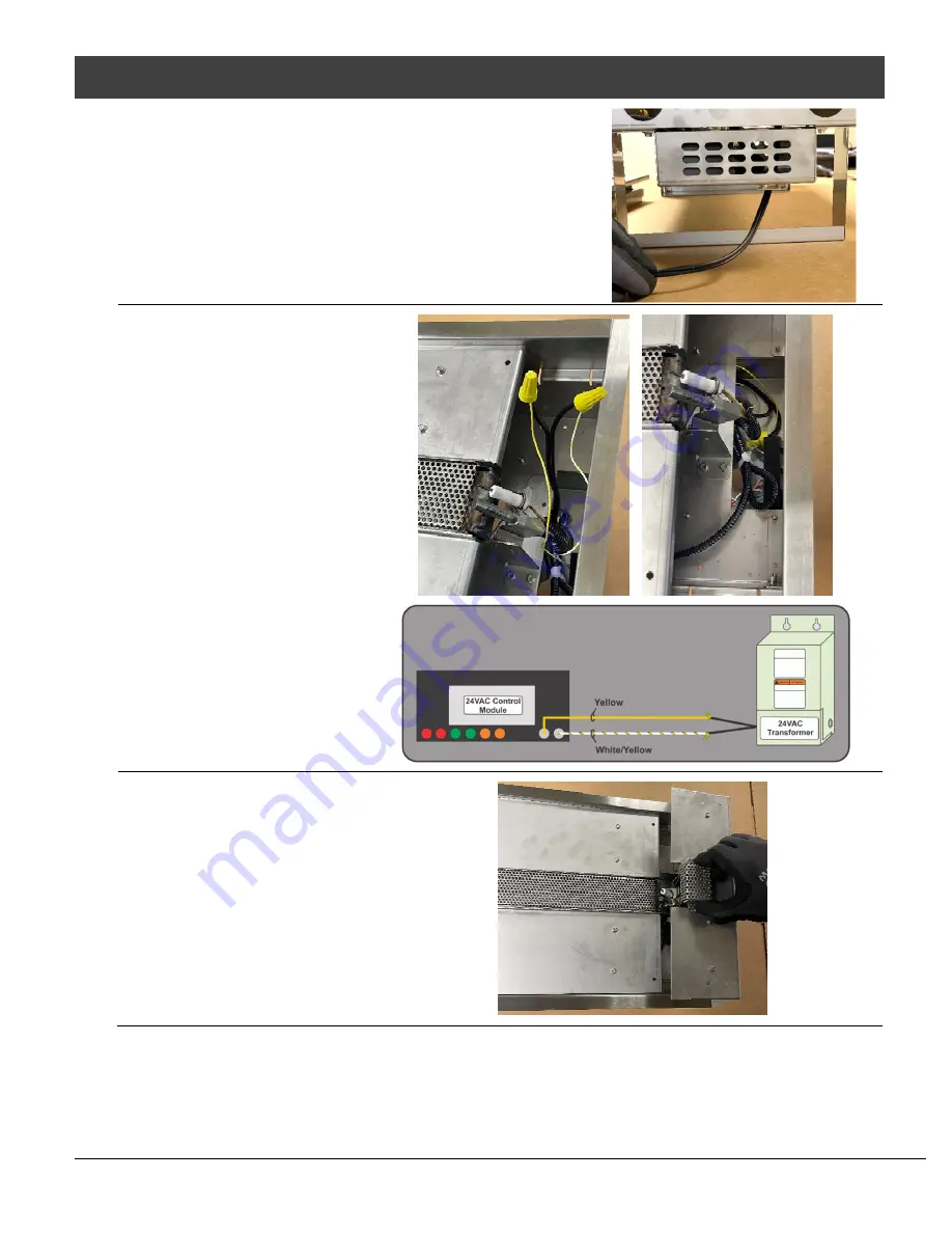
  Route the wires from the 24VAC transformer through the 

strain relief at the bottom of the electrical box (below the 
pilot).  Use listed low voltage wiring.  Make sure to 
provide slack in the electrical line for removal and service. 


  Use wire nuts to 

connect the wires from 
the 24VAC transformer 
to the yellow and the 
yellow/white striped 
wires on the control 
module (polarity does 
not matter for this 
connection).  When the 
connections are secure, 
coil the wires and push 
them back into the 
electrical box. 


  Reinstall the media tray cover and pilot shield. 


  The appliance uses approximately 40 watts during startup (1.6 amps at 24 VAC).  Make sure the circuit 

and wires are sized appropriately.  The appliance requires a minimum of 22 VAC to operate (if the voltage 
drops below this, the appliance may not start). 


Summary of Contents for Fire Garden 94900430

Page 1: ...ppliance WARNING For outdoor use only Installation and service must be performed by a qualified installer service agency or the gas supplier WARNING Improper installation adjustment alteration service...

Page 2: ...ber will be needed in case you require service of any type To receive full warranty coverage you will need to show evidence of the date of purchase Visit traviswarranty com to register your appliance...

Page 3: ...nection Requirements 19 24VAC Transformer 19 Wiring Installation 19 Using More than One 24 volt Appliance 21 Wiring Multiple Transformers to One Switch 21 Wiring Multiple Appliances to One Transformer...

Page 4: ...ved for either natural gas NG or propane LP Burning the incorrect fuel will void the warranty and safety listing and may cause an extreme safety hazard Direct questions about the type of fuel used to...

Page 5: ...60 Hz 1 6 Amps Appliance Weight 36 Linear Burner 30 lbs 13 6kg 60 Linear Burner 50 lbs 22 7kg 120 Linear Burner 100 lbs 45 4kg Gas Specifications All Linear Burners Gas Pressures NG LP Manifold Pressu...

Page 6: ...6 Features and Specifications Travis Industries Inc 4 11 22 1538 Outdoor Linear Burners Linear Burner Dimensions 36 Linear Burner 60 Linear Burner...

Page 7: ...perate on natural gas or propane LP This appliance requires a switched 110v AC GFCI ground fault circuit interrupter protected power supply This circuit provides power to the 24v AC transformer Notify...

Page 8: ...y Electrical The appliance uses 24VAC power and draws approximately 1 6 amps Make sure the circuit and wiring are appropriately sized see diagrams starting on pg 21 If multiple appliances are powered...

Page 9: ...ded of boxes needed 36 Linear Burner 15 lbs 6 8kg 2 60 Linear Burner 25 lbs 11 34kg 3 120 Linear Burner 50 lbs 22 68kg 5 Travis Industries offers the following Ember Rock Option Ember Rock sku 9450096...

Page 10: ...The sidewalls may be parallel as in a breezeway or at right angles to each other Within a partial enclosure that includes an overhead cover and three sidewalls as long as 30 percent or more of the hor...

Page 11: ...Installation qualified installers only 11 Travis Industries Inc 4 11 22 1538 Outdoor Linear Burners Clearances 36 60 Linear Burners ONLY 120 Linear Burner ONLY...

Page 12: ...12 Installation qualified installers only Travis Industries Inc 4 11 22 1538 Outdoor Linear Burners Minimum Framing Dimensions 36 Linear Burner 60 Linear Burner 120 Linear Burner...

Page 13: ...lations where the outer flange of the linear burner rests on the top surface of the block or capstone and the windbreak glass sits on the same surface Recessed Installations use brackets that are inst...

Page 14: ...e pit enclosure The minimum surface needed for the windbreak to be properly supported is shown below NOTE Keep the size of the finish material in mind when planning your installation and before buildi...

Page 15: ...cool Failure to provide this ventilation will create a severe fire risk The ventilation grilles must be installed within 24 of the appliance Enclosure Ventilation Overview The linear burner enclosure...

Page 16: ...o the enclosure cavity The grilles must have 1 4 screen to prevent debris etc from entering the enclosure The grilles should not be placed in a location where they could become blocked The ventilation...

Page 17: ...of that system at test pressures in excess of 1 2 psig For pressures less than 1 2 psig isolate the gas supply piping by closing the manual shut off valve Leak test all gas line joints and the gas co...

Page 18: ...codes and requirements of the authority having jurisdiction If the information in these instructions is not followed exactly a fire explosion or production of carbon monoxide may result causing proper...

Page 19: ...24 volt appliances may be placed on a single circuit Each appliance uses 24VAC at approximately 1 6 amps Make sure the circuit and wiring is appropriately sized see diagrams starting on pg 21 If multi...

Page 20: ...onnect the wires from the 24VAC transformer to the yellow and the yellow white striped wires on the control module polarity does not matter for this connection When the connections are secure coil the...

Page 21: ...ut how the appliances will be used and if they need to be able to be controlled separately or if it would be more convenient to control them all using one switch The following pages show examples of m...

Page 22: ...e Appliances to One Transformer The manner in which you wire the appliances to the transformer affects the maximum length of wire and wire gauge Make sure to determine the wire configuration before in...

Page 23: ...for the entire installation If you have one 80 length and three 20 lengths your wire length would be 140 24 Volt Lead of appliances on branch Wire 2 3 4 5 6 14 GA min 0 0 0 0 0 max 113 71 49 37 28 12...

Page 24: ...566 max 897 max 1168 Not available on some transformers Wiring Examples Daisy Chain Installations When using 3 appliances on one branch 14 ga wire and 150 of wire use the 28V Lead When using 4 applia...

Page 25: ...ries Placing Crushed Glass on the Burner and Center Media Trays Glass Quantity Needed 36 Linear Burner 10 lbs 4 54 kg 60 Linear Burner 25 lbs 11 34 kg 120 Linear Burner 50 lbs 22 64 kg 1 Level Cup 8 f...

Page 26: ...t prior to installing the Rock Embers in order to disguise the stainless steel so it is not as noticeable between the Rock Embers 1 Determine the amount of small Rock Embers needed for the appliance b...

Page 27: ...nd Media Trays Small Tumbled Stone Quantity Needed 36 Linear Burner 50 lbs 22 7 kg 60 Linear Burner 70 lbs 31 8 kg 120 Linear Burner 140 lbs 63 6 kg NOTE We recommend painting the burner and media tra...

Page 28: ...tion it on its edge on a flat surface Attach the top brackets as shown below Use a standard screwdriver to secure the brackets to the glass panel Take care not to overtighten NOTE The brackets should...

Page 29: ...to the properly oriented side pieces and secure the brackets to the glass Repeat this step with the other side glass panel 7 When all the clamps are secure turn the assembly over and place it on the f...

Page 30: ...en turned on to the appliance The appliance will ignite and the thermopile will signal the control module that the appliance is lit and the igniter will then turn off NOTE In rare cases the appliance...

Page 31: ...itch to supply power to the appliance The appliance will automatically light when power is supplied The location of the switch is specific to your installation If the wall switch will be located where...

Page 32: ...is normal Your appliance is designed to be easily cleaned and maintained The most common maintenance that your appliance will require is cleaning the glass windbreaks Clean with glass cleaner or warm...

Page 33: ...ay To access the components follow the steps below Removing the Media Trays Remove the windbreak glass and all the crushed glass media if already installed Remove the 4 screws that secure the media tr...

Page 34: ...y in the center of the appliance Use a manometer to test the gas manifold gas pressure Removing the Burner NOTE If you are accessing the gas or electrical connections you do not need to remove anythin...

Page 35: ...attaching the pilot to the control module below When you have removed all the slack from the wires reach down into the electrical box with your other hand and free the control module from the Velcro...

Page 36: ...es be done by a qualified technician THIS APPLIANCE IS NOT USER SERVICEABLE Contact your dealer for service Inspect the pilot flame The top 1 4 of both the thermopile and igniter should be within the...

Page 37: ...lacement Parts 36 Linear Burner WIND GUARD GLASS FRONT REAR 38 7 8 x 6 Qty 1 250 05774 60 Linear Burner WIND GUARD GLASS FRONT REAR 62 7 8 x 6 Qty 1 250 05708 120 Linear Burner WIND GUARD GLASS FRONT...

Page 38: ...raw appliance in startup Appliance Lights During Ignition Sequence then Goes Out During Normal Operation Dirty Air Channel or Burner Thermopile has worn out Remove glass and clean soot from burner and...

Page 39: ...h as discoloration Also excluded is damage to the unit caused by abuse improper installation modification of the unit drilling of the orifices or the use of fuel other than that for which the unit is...

Page 40: ...40 Wiring Diagram Travis Industries Inc 4 11 22 1538 Outdoor Linear Burners Wiring Diagram...

Page 41: ...Wiring Diagram 41 Travis Industries Inc 4 11 22 1538 Outdoor Linear Burners...

Page 42: ...Requirements 17 Gas Specifications 5 Glass Cleaning 32 Installation Warnings 7 Landscaping Block Enclosures 13 Linear Burner Dimensions 6 Location of Controls 31 LP Conversion 18 Maintaining Your Appl...

Reviews: