background image

 Warranty 

25 

© Travis Industries, Inc. 

5/21/20 - 1534 

Tempest Lantern 24v 

To register your TRAVIS INDUSTRIES, INC. 1 Year Limited Warranty, complete the enclosed Warranty card and mail it within 

ten (10) 

days of the 

appliance purchase date to: TRAVIS INDUSTRIES, INC., 4800 Harbour Pointe Blvd. SW, Mukilteo, WA 98275. TRAVIS INDUSTRIES, INC. warrants 
this gas appliance (appliance is defined as the equipment manufactured by Travis Industries, Inc.) to be defect-free in material and workmanship to 
the original purchaser from the date of purchase as follows: 

Check with your dealer in advance for any costs to you when arranging a warranty call. Mileage or service charges 

are not covered by this warranty. This charge can vary from store to store. 

Warranty 

90 Day Coverage: PARTS & LABOR 

Burner Assembly: 

Burner, Venturi, Flame Spreader, Orifice, Gas valve 

Glass: 

Glass (breakage from thermal shock only) 

Accessories: 

Wall mount bracket, in-ground post, and pillar post 

One-Way Freight Allowance: 

One-way freight allowance on pre-authorized repair done at factory is 
covered. 

Electrical Components: 

Flame Sensor, Transformer, Wire Harness, Control Module, Igniter 

Exclusions: Paint and Finish 

Year 1 Coverage: PARTS & LABOR 

Burner Assembly: 

Burner, Venturi, Flame Spreader, Orifice, Gas valve 

Glass: 

Glass (breakage from thermal shock only) 

Accessories: 

Portable base (including post and tank cover), wall mount bracket, 
in-ground post, and pillar post 

One-Way Freight Allowance: 

One-way freight allowance on pre-authorized repair done at 
factory is covered. 

Exclusions: Paint and Finish, Electrical Components 

CONDITIONS & EXCLUSIONS 

1. This new gas appliance must be installed by a qualified gas appliance technician. It must be installed, operated, and maintained at all times in accordance with the 

instructions in the Owner’s Manual. Any alteration, willful abuse, accident, neglect, alteration, misapplication or misuse of the product shall nullify this warranty. 

2. This warranty is nontransferable, and is made to the ORIGINAL purchaser, provided that the purchase was made through an authorized TRAVIS dealer. 
3. Discoloration and some minor expansion, contraction, or movement of certain parts and resulting noise, is normal and not a defect and, therefore, not covered under 

warranty. The installer must ensure the appliance is burning as per the rating tag at the time of installation. Over-firing (operation above the listed BTU rate) of this 
appliance can cause serious damage and will nullify this warranty. 

4. This warranty does not cover damage to the finish, such as scratches, dents, discoloration, rust or other weather damage, after purchase. 
5. Travis Industries will not be responsible for inadequate performance caused by environmental conditions such as nearby trees, buildings, roof tops, wind, hills or 

mountains or other influences from mechanical systems such as fans, etc. 

6. This Warranty is void if: 

a. The unit has been operated in atmospheres contaminated by chlorine, fluorine or other damaging chemicals. 
b. The unit is subject to submersion in water. 

7. Exclusions to this 1 Year Warranty include: injury, loss of use, damage, failure to function due to accident, negligence, misuse, improper installation, alteration or 

adjustment of the manufacturer's settings of components, lack of proper and regular maintenance, damage incurred while the appliance is in transit, alteration, or act of 
God. 

8. This 1 Year warranty excludes damage caused by normal wear and tear, such as discoloration. Also excluded is damage to the unit caused by abuse, improper 

installation, modification of the unit, drilling of the orifices, or the use of fuel other than that for which the unit is configured. Units are shipped for either natural gas or 
propane. Confirm fuel configuration with your installer. 

9. Damage to stainless steel surfaces caused by fingerprints, scratches, melted items, or other external sources left on the stainless steel from the use of cleaners is not 

covered in this warranty. 

10. TRAVIS INDUSTRIES, INC. is free of liability for any damages caused by the appliance, as well as inconvenience expenses and materials. Incidental or consequential 

damages are not covered by this warranty. In some states, the exclusion of incidental or consequential damage may not apply. 

11. This warranty does not cover any loss or damage incurred by the use or removal of any component or apparatus to or from the gas appliance without the express 

written permission of TRAVIS INDUSTRIES, INC. and bearing a TRAVIS INDUSTRIES, INC. label of approval. 

12. Any statement or representation of TRAVIS products and their performance contained in TRAVIS advertising, packaging literature, or printed material is not part of this 

1 year warranty. 

13. This warranty is automatically voided if the appliance’s serial number has been removed or altered in any way.  
14. No dealer, distributor, or similar person has the authority to represent or warrant TRAVIS products beyond the terms contained within this warranty. TRAVIS 

INDUSTRIES, INC. assumes no liability for such warranties or representations. 

15. Travis Industries will not cover the cost of the removal or re-installation.  
16. If for any reason any section of this warranty is declared invalid, the balance of the warranty remains in effect and all other clauses shall remain in effect. 
17. THIS 1 YEAR WARRANTY IS THE ONLY WARRANTY SUPPLIED BY TRAVIS INDUSTRIES, INC., THE MANUFACTURER OF THE APPLIANCE. ALL OTHER 

WARRANTIES, WHETHER EXPRESS OR IMPLIED, ARE HEREBY EXPRESSLY DISCLAIMED AND PURCHASER’S RECOURSE IS EXPRESSLY LIMITED TO THE 
WARRANTIES SET FORTH HEREIN. 

IF WARRANTY SERVICE IS NEEDED: 

1. If you discover a problem that you believe is covered by this warranty, you MUST REPORT it to your TRAVIS dealer WITHIN 30 DAYS, giving them proof of purchase, 

the purchase date, and the model name and serial number. 

2. Travis Industries has the option of either repairing or replacing the defective component. 
3. If your dealer is unable to repair your appliance's defect during the warranty period, they will process a warranty claim through TRAVIS INDUSTRIES, INC.  The dealer 

will require you to supply a copy of your receipt showing the date of the appliance's purchase and the serial number on your appliance. The appliance will then be 
shipped, freight charges prepaid, to TRAVIS INDUSTRIES, INC.  TRAVIS INDUSTRIES, INC., at its option, will repair or replace the appliance free of charge if it is 
found to be defective in material or workmanship within the time frame stated within this warranty.  TRAVIS INDUSTRIES, INC. will return your appliance, freight 
charges prepaid (years 1 to 3 only) by TRAVIS INDUSTRIES, INC., to your regional distributor, or dealership. 


Summary of Contents for Tempest

Page 1: ...use shall not be stored in the vicinity of this or any other appliance DANGER FIRE OR EXPLOSION HAZARD If you smell gas Shut off gas to the appliance Extinguish any open flame If odor continues leave the area immediately After leaving the area call your gas supplier or fire department Failure to follow these instructions could result in fire or explosion which could cause property damage personal ...

Page 2: ...ve Appliances The listing label is chained to the appliance A copy is shown to the right Important Registration and Service Information No other Tempest Lantern has the same serial number as yours The serial number is on the safety label attached by a chain near the control panel This serial number will be needed in case you require service of any type To receive full warranty coverage you will ne...

Page 3: ...lation 10 24VAC Transformer 10 Wire Configuration Direct Run vs Daisy Chain Installations 10 Lantern Wiring Diagram 11 Wiring Multiple Transformers to One Switch 12 Wiring Multiple Lanterns to One Transformer 13 Daisy Chain Example 13 Direct Run Example 13 Daisy Chain Wire Length Chart 14 Direct Run Wire Length Chart 15 Wiring Examples 15 Daisy Chain Installations 15 Direct Run Installations 15 Po...

Page 4: ... LP Burning the incorrect fuel will void the warranty and safety listing and may cause an extreme safety hazard Direct questions about the type of fuel used to your dealer A label is placed on the control panel to show which fuel the Lantern is designed for in addition NG units have 25 burner holes LP units have 49 burner holes Contact your local building officials to obtain a permit and informati...

Page 5: ...ll Mount Post Mount Pillar Mount Gas Specifications NG LP Input Rating BTU h 20 000 20 000 Orifice Size DMS 50 55 Burner Ports 25 Holes 49 Holes Manifold Pressure 7 wc 11 wc Max Inlet Pressure 7 wc 11 wc Electrical Specifications 24 Volts AC 1 6 amps on startup 40 watts on startup Dimensions NOTE Side clearances are measured from the glass Top clearances are measured from the glass frame 19 1 8 2 ...

Page 6: ...rmation You provide them page 2 The requirements listed below are divided into sections All requirements must be met simultaneously The order of installation is not rigid the qualified installer should follow the procedure best suited for the installation Packing List Main Assembly Burner Top Rain Cap Control Cover pre installed 4 6 x 1 Screws used to secure control module to wall or other structu...

Page 7: ...re the circuit and wiring is appropriately sized see diagram on pg 12 If multiple Lanterns are powered through a single switch the control modules for each of the individual Lanterns may be daisy chained together make sure polarity is correct see pg 16 Make sure to leave slack in the electrical line so the head can be removed for service 5 For outside post and pillar installations route a stainles...

Page 8: ...ern in these locations are recommended In places where the controls beneath the Lantern may be submerged under water Submerging of any part of its controls may require complete replacement of the controls Clearances The distance from ground level to the top of the Lantern shall be a minimum of 7 ft 2 1M where installed within 2 feet 0 6M of public walkways e g sidewalk shared walkway between two h...

Page 9: ...nd Handling Code B149 2 as applicable Consult your local gas supplier or propane gas dealer for code regulations and recommended procedures The Lantern and gas control module must be disconnected from the gas supply piping during any pressure testing of that system at test pressures in excess of 1 2 psig For pressures less than 1 2 psig isolate the gas supply piping by closing the manual shut off ...

Page 10: ...or wall mount Make sure to provide slack in the electrical line for removal and service Each Lantern uses approximately 40 watts during startup 1 6 amps at 24VAC Make sure the circuit and wire are sized appropriately The Lantern requires a minimum of 21VAC to operate if voltage drops below this the Lantern may not start 24VAC Transformer This Lantern must be used with a 24VAC switched circuit The ...

Page 11: ... ood H e d chuck as m uch w ood as a w oodchuck coul d chuck i f a w oodchuck coul d chuck w ood I have no i dea w hat t hi s st i cker says but I w i l l put i n t hi s t ext t o m ake i t l ook m ore real i st i c P l ease make sure you r ead t he act ual l abel so you don t hurt your sel f Thank you f or your at t ent i on t o t hi s i m por t ant m at t er I have no i dea w hat t hi s st i cke...

Page 12: ...34 Tempest Lantern 24v Wiring Multiple Transformers to One Switch Multiple 24VAC transformers may be wired to a single switch see diagram below WA R N I N G WA R N I N G A T T E N T I O N A T T E N T I O N 1 1 Hot Black Common White Ground Green Po wer Su pply GF CI Protected ...

Page 13: ...to determine the wire configuration before installation NOTE You may use both direct run and daisy chain configurations Polarity must be maintained in all multiple Lantern installations Failure to maintain polarity will result in damage to the control module Daisy Chain Example Direct Run Example 1 Hot Black Common White Ground Green Power Supply GFCI Protected WA R N I N G A T T E N T I O N 1 Hot...

Page 14: ...gths your wire length would be 140 24 Volt Lead Of Lanterns On Branch Wire 2 3 4 5 6 14 G min 0 0 0 0 0 max 113 71 49 37 28 12 G min 0 0 0 0 0 max 173 108 75 55 43 10 G min 0 0 0 0 0 max 266 165 115 85 65 26 Volt Lead Of Lanterns On Branch Wire 2 3 4 5 6 14 G min 27 10 1 0 0 max 184 118 85 65 51 12 G min 41 16 2 0 0 max 281 179 129 99 79 10 G min 63 23 3 0 0 max 432 276 198 151 121 28 Volt Lead Of...

Page 15: ...ormers Wiring Examples Daisy Chain Installations When using 3 Lanterns on one branch 14 G wire and 150 of wire use the 28V Lead When using 4 Lanterns on one branch 10 G wire and 100 of wire use the 24V Lead Direct Run Installations When using a Lantern on a 200 run 14 G wire use the 24V Lead When using 6 Lanterns each on a 200 run 14 G wire use the 24V Lead How to Determine Wire Gauge When purchas...

Page 16: ...important that the polarity between the Lanterns are connected in parallel all yellow wires connected together and all white yellow stripe wires connected together Polarity between the Lanterns and the transformer does not matter Yellow White Yellow Yellow White Yellow 24V AC Transformer Yellow White Yellow Yellow White Yellow 24V AC Transformer Correct Incorrect WRONG DO NOT ALLOW A YELLOW WIRE T...

Page 17: ...ack tape to protect the post from scratches NOTE When installing the post make sure the post is positioned with the mounting holes 45 offset from the front The post mount has obround holes that allow 20 of rotation 10 in each direction b Attach the gas and electrical lines WARNING Take care when handling the Lantern assembly to not damage the gas or electrical line c Attach the Lantern to the post...

Page 18: ...he hole on the burner top b Slide the glass panels into place by aligning each panel with one of the slots in the top plate of the Lantern Support the glass panels as you lower them into place to avoid damaging them HINT Make sure the glass is clean before installing and handle with soft gloves or other non marking material e g paper towel c Place the rain cap on the top of the Lantern glass assem...

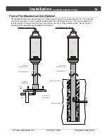
Page 19: ...ptional post base kit If the post is placed in a remote location it may be sunk into the ground using concrete or other suitable means See the post or post base kit for assembly and installation instructions Post Mount included with torch Post Base separate kit Deck Mount post or pillar Gas 24V 24V Elec Elec Line Line Line Deck Surface or equivalent Post Mount included with torch Free Standing Pos...

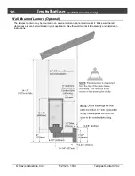
Page 20: ...1534 Tempest Lantern 24v Wall Mounted Lantern Optional The tempest Lantern may be mounted to an external wall an optional wall mount kit Make sure that all clearances are can be maintained in your application See the wall mount kit for assembly and installation instructions ...

Page 21: ...conds then re start the 35 second ignition sequence The control module will try to re start the Lantern a total of 3 times If it fails to light after three tries the Lantern will then shut off To re start turn the switch off wait 3 seconds then turn the switch on Lantern in Operation The Lantern once lit will stay lit until power to the Lantern is turned off If gas flow is interrupted or if wind b...

Page 22: ... a car windshield It is special glass and if you break one or need to replace a piece use only 3 16 thick tempered glass supplied by your Tempest Lantern dealer To inspect for or clean debris out of the inside of your Lantern remove one piece of glass This will provide access to the inside of your Lantern Once your glass piece is out remove the pyramid shaped piece with the rings on the top by lif...

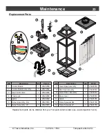
Page 23: ...rol Module 1 250 04553 2 Control Module Assembly 1 250 04552 3 Gas Control Valve 1 250 04554 4 Thermopile 1 250 04550 5 Ignitor 1 250 04549 6 Burner Assembly NG 1 250 05516 6 Burner Assembly LP 1 250 05515 ID Description Qty Part 7 Lower Base Assembly 1 250 05518 8 Rain Cap Assembly 1 250 05512 9 Glass Frame Assembly 1 250 05513 10 Base Cover 1 250 05514 11 Glass 4 250 01251 12 Flame Spreader NG 1...

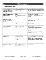
Page 24: ...eplace thermopile Flames are too short under 6 The gas supply pressure to the appliance is too low Depleted LP cylinder Gas supply lines or gas regulators do not have enough capacity This may be due to other appliances in the house using up the available capacity e g pool heaters furnaces hot water tanks etc Flames are not Spiral Lantern was just turned on Windy Condition It takes 5 to 10 minutes ...

Page 25: ...ings of components lack of proper and regular maintenance damage incurred while the appliance is in transit alteration or act of God 8 This 1 Year warranty excludes damage caused by normal wear and tear such as discoloration Also excluded is damage to the unit caused by abuse improper installation modification of the unit drilling of the orifices or the use of fuel other than that for which the un...

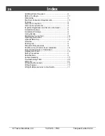
Page 26: ...llation Options 5 Installation Warnings 6 Listing Details 2 Maintaining Your Lantern 18 Operating Instructions 17 Optional Rain Cap 16 Overview 2 Packing List 6 Placement Requirements 8 Post Mount and Control Cover Installation 14 Recommended Order of Installation 7 Replacement Parts 19 Safety Precautions 4 Specifications 5 Lantern Assembly 15 Troubleshooting Table 20 Warranty 21 Winterizing the L...

Reviews: