3
4
4. INSTALLATION AND SYSTEM CONFIGURATION
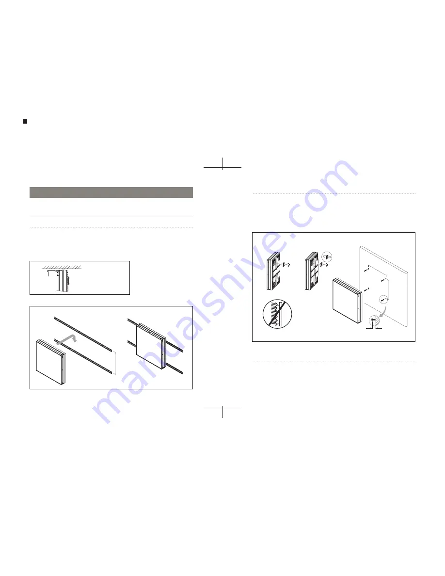
4-1 MOUNTING — DIN RAIL
•
Use a pencil or chalk to mark the horizontal alignment before installation.
•
Mount the DIN rails to the wall, leaving minimum clearance (Fig 1).
•
Hang the panel onto the DIN rail as shown in Fig 2.
1 colors
PANTONE BLACK M
Fig 2: Mounting onto DIN Rail
Fig 1: Mounting Clearance
CAUTION – DO NOT INSTALL THE PANEL IF THE COVER SHIELD IS DAMAGED.
4-3 CONNECTION
The 64PXL panel can be controlled by the Traxon Micro Server or standard DMX512 controllers.
Each Micro Server can control up to four 64PXL panels (two panels per DMX512 output).
Connect the Micro Server to the 64PXL panels as shown in Fig 4.
4-2 MOUNTING — DIRECT TO WALL
•
Use a pencil or chalk to mark the horizontal alignment before installation.
•
Install four screws to the wall, leaving minimum clearance (Fig 1).
•
Reverse the 4 mounting plates on the Panel.
•
Hang the panel on the wall as shown in Fig 3.
Fig 3: Direct Screw Mounting to Wall
DO NOT MOUNT ON
UNEVEN SURFACE
1. Unscrew and detach
the 4 mounting brackets.
2. Reverse and screw back on
the 4 mounting brackets.
3. Screw and hang panel.
340mm/13.4”
340mm/13.4”
Min. 6mm/0.24”
Allow sufficient ceiling
clearance when mounting.
Min. 10mm
340mm/13.4”
35mm x 7.5mm DIN rail
(EN50022, BS5584, DIN 46277-3)
(Not included)


