background image

6

drilled; See also the instructions below under "Mounting to a Drilling Stand"

INTRODUCTION

This machine is for the intended purpose of diamond core drilling of concrete, masonry, stone and similar 
materials. It must always  be mounted on a drilling stand. This machine is for professional use only and only 
trained personnel may operate this machine.
All other uses which are not for the intended purpose are prohibited.

It is equipped with a water feed system which is required for the diamond core drilling process. A  PRCD 
interrupter (portable residual current device) which must be used at all times. 
It is equipped with a three or a four speed mechanical gearbox (depending on model) for different core drill 
size ranges and features  a mechanical safety clutch. 
The motor has electronics for soft start, overload protection and thermal (overheating) protection. There is a 
pulse function overload warning to alert the operator of load and overload conditions.
 
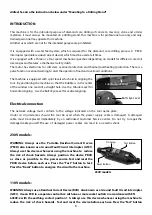
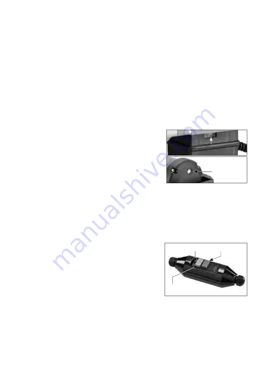
The machine is equipped with spirit levels which aid in aligning the 
tool.  By positioning the machine so that the bubble is in the center 
of the window one can drill a straight hole. Use the  Tubular Level for 
horizontal aligning.   Use the Bull's Eye Level for vertical aligning.

Electrical connection

The  network  voltage  must  conform  to  the  voltage  indicated  on  the  tool  name  plate. 
Under  no  circumstances  should  the  tool  be  used  when  the  power  supply  cable  is  damaged.  A  damaged  
cable  must  be  replaced  immediately  by  an  authorized  Customer  Service  Center.  Do  not  try  to  repair the 
damaged cable yourself. The use  of  damaged  power  cables  can  lead  to  an  electric shock.

230V models:

WARNING: Always use the  Portable Residual Current Device 
(PRCD) also known as a Ground Fault Circuit Interrupter (GFCI). 
Always use this device whenever using the machine to  reduce  
the  risk  of  shock  hazards.  Always  position  the  device  PRCD  
as  close  as  possible  to  the  power source. Test and reset the 
PRCD device before each use. Press the “Test” button to test. 
Press the “Reset” button to energize  the circuit to the machine.

110V models: 

WARNING: Always use a Residual Current Device (RCD)  also known as a Ground Fault Circuit Interrupter 
(GFCI).  Use an RCD in a separate control box with one or more socket outlets in accordance with EN 
60309-2 with the earthing contact position 1 h. Always use this device whenever using the machine to  
reduce  the  risk  of  shock  hazards.  Test and  reset the   device before each use. Press the “Test” button 

Tubular Spirit Level

Bull's Eye Level

Test Button

Reset Button

 On Lamp

230V models

Summary of Contents for DBM-32-3

Page 1: ...RE DRILLING MACHINES OPERATING MANUAL CAUTION Machine equipped with overheat thermal protection When the thermal protection kicks in always remove from the work piece and run at no load for at least 3 minutes to allow motor to cool before returning to operation DBM 32 3 3 SPEED MODEL DBM 32 4 4 SPEED MODEL ...

Page 2: ...0 1000 Drilling Capacity Ø400mm 16 Ø350mm 14 Ø300mm 12 Ø250mm 10 Dimensions 550mm x 155mm x 210mm Gear OilType 90W Gear Oil Capacity 625ml SpindleThread 1 1 4 UNC male 1 2 BSP female Protection Class Class 1With RCD Weight 13 5kg 12 9kg 12 9kg 12 9kg 4 SPEED MODELS 3 SPEED MODELS Low RPM Gear Selectors Spindle Gear Box Motor Unit Quick Release Water Coupling Tail Handle Tubular Spirit Level On Off...

Page 3: ...ase the risk of electric shock e When operating a power tool outdoors use an extension cord suitable for outdoor use Use of a cord suitable for outdoor use reduces the risk of electric shock f If operating a power tool in a damp location is unavoidable use a residual current device RCD protected supply Use of an RCD reduces the risk of electric shock 3 Personal safety a Stay alert watch what you a...

Page 4: ...lignment or binding of moving parts breakage of parts and any other condition that may affect the power tool s operation If damaged have the power tool repaired before use Many accidents are caused by poorly maintained power tools f Keep cutting tools sharp and clean Properly maintained cutting tools with sharp cutting edges are less likely to bind and are easier to control g Use the power tool ac...

Page 5: ...r to prevent damage WARNING Pull the plug out of the socket before making device settings or changing accessories Many accidents are caused by accidental starting of power tools When mounting the stand fix the base to a firm level surface or wall The power tool cannot be guided evenly and safely if the base can slip or shake This diamond core drill cannot be used for overhead drilling WARNING Haza...

Page 6: ...zontal aligning Use the Bull s Eye Level for vertical aligning Electrical connection The network voltage must conform to the voltage indicated on the tool name plate Under no circumstances should the tool be used when the power supply cable is damaged A damaged cable must be replaced immediately by an authorized Customer Service Center Do not try to repair the damaged cable yourself The use of dam...

Page 7: ... outside male thread is 1 1 4inch UNC the inside female thread is 1 2 inch BSP Ensure both the core bit and the machine spindle are clean Any debris could cause excessive run out of the mounted core bit Excessive run out can cause premature failure of the core bit and or a safety hazard Tighten the bit to the spindle using two wrenches Only use correct sized wrenches to avoid damage to the spindle...

Page 8: ... drilling Never use this machine without water feed To connect the water supply Attach the quick release water coupling to a water hose WARNING Never allow water to enter the motor It could lead to an electric shock WARNING Check all connections of the water feed system to ensure there are no leaks Inspect hoses and other critical parts which could deteriorate WARNING The maximum water pressure sh...

Page 9: ...d 3 n0 1000 min n 620 min 50 180mm 2 7 4 SPEED MODELS RECOMMENDED BIT Ø Speed 1 AD n0 385 min n 225 min 300 400mm 12 16 Speed 2 AC n0 530 min n 300 min 180 300mm 7 12 Speed 3 BD n0 975 min n 565 min 125 180mm 5 7 Speed 4 BC n0 1340 min n 780 min 40 125mm 1 1 2 5 Recommended bit size based on average hardness concrete Speeds will vary with different material hardnesses For reinforced concrete speed...

Page 10: ...osition before plugging in WARNING Whenever there is an interruption to the power supply turn the switch to the OFF position to avoid an accidental restart when power returns 110V models This machine has a relay type rocker switch Press the switch to the on position to turn on Press the switch to the off position to turn off Since this is a relay type switch if there is an interruption to the powe...

Page 11: ... floor the core will fall down Take precautions to avoid injury or damage below NOTE When drilling with a new bit for the first time use less than normal feed pressure for a time until it breaks in DRILLING INSTRUCTIONS 1 Press the Reset button on the PRCD interrupter device to energize the circuit to the machine Then turn the machine on 2 Open the water valve slightly and very gently begin the cu...

Page 12: ...y or the diamond segments will become glazed Keep the bit steadily working but don t be abusive or give the bit shock impacts into the work surface If the cut is very deep the core plug may be obstructing the flow of cooling water In this case stop drilling and chisel out the core plug before continuing CAUTION If the bit gets stuck do not try to rock it loose by turning the switch on and off That...

Page 13: ...usually caused by 1 A bit with too much runout SOLUTION Replace bit 2 A bit with diamond segments broken off SOLUTION Replace bit 3 Shifted base or loose gibs SOLUTION Retighten mountings or adjust gibs as needed KEEP TOOL CLEAN Wipe down the machine at the end of each work day with a damp cloth NEVER use solvents to clean plastic parts They could possibly dissolve or otherwise damage the material...

Page 14: ...he brushes should be checked The auto stop brush design protects the motor by stopping the machine before the carbon brushes are completely worn out Caution Always replace the brushes as a pair To replace 1 Remove the 4 screws and remove the motor tail cover 2 Using pliers rotate the brush spring out of the way and slide the old carbon brush out of the brush holder 3 Unscrew the screw to remove th...

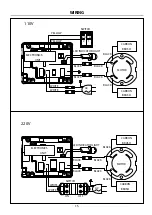
Page 15: ... BLACK YELLOW SWITCH YELLOW WHITE MOTOR CARBON BRUSH CARBON BRUSH BLACK BLACK BLACK BLACK ELECTRONICS UNIT BLACK BLACK MOTOR CARBON BRUSH CARBON BRUSH BLACK BLACK BLACK BLACK AC SWITCH ON OFF WHITE WHITE 110V 220V LED INDICATOR LIGHT LED INDICATOR LIGHT ...

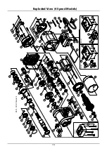
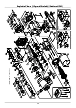
Page 16: ...5 62 62 67 47 46 48 49 50 51 100 46 45 54 30 29 28 31 32 27 13 72 75 76 105 76 83 82 80 81 80 79 78 74 19 22 21 03 02 01 12 05 34 33 20 18 04 24 24 41 43 44 36 35 42 38 38 44 15 88 59 25 94 10 10 FOR 110V FOR 220V 11 11 09 08 12 96 08 88 95 98 99 98 99 97 102 104 103 A1 Optional 73 97 106 107 108 109 ...

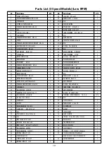
Page 17: ...x12T 1 44 BALL BEARING 6200 2 45 NEEDLE BEARING HK 1010 1 46 INTERNAL CIRCLIP IS18 2 47 SLIDER GEAR CD M1 75x36T 1 48 LAY GEAR M1 5x46T 1 49 COUNTERSHAFT GEAR M2 0x26T 1 50 PARALLEL KEY 5x5x25 1 51 PARALLEL KEY 6x6x15 1 NO Parts Name Q TY 52 53 N A 54 NEEDLE BEARING TA1815 1 55 INTERNAL CIRCLIP IS25 2 56 SLIDER GEAR AB M2 0x28T 1 57 OUTPUT GEAR M2 0x40T 1 58 CLUTCH NUT M27xP1 0x7 8T 1 59 THRUST BE...

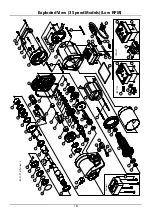
Page 18: ... 55 56 60 63 47 49 48 50 51 46 45 54 13 68 71 72 98 72 80 79 77 78 77 76 75 69 70 19 22 21 02 01 12 05 34 33 20 18 04 24 24 41 43 44 87 36 35 42 38 38 74 44 95 14 15 57 26 30 29 28 31 32 27 10 10 FOR 110V FOR 220V 11 11 25 09 08 12 88 03 81 90 91 08 49 89 81 92 93 94 96 97 A1 Optional 99 ...

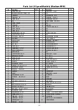
Page 19: ...T x 20T x 13T 1 44 BALL BEARING 6200 ZZ 2 45 NEEDLE BEARING TLA 1010 1 46 INTERNAL CIRCLIP IS 14 1 47 COUNTERSHAFT SET 1 48 SPINDLE GEAR M1 5 x 38T 1 49 INTERNAL CIRCLIP IS 18 2 NO Parts Name Q TY 50 LAY GEAR M1 5 x 45T 1 51 PARALLEL KEY 5 x 5 x 40 1 52 53 N A 54 NEEDLE BEARING 1 55 NYLOOK NUT M20 x P1 5 1 56 OUTPUT GEAR M2 0 x 41T 1 57 THRUST BEARING Ø30 x Ø47 x 2 1 58 N A 59 GEAR HOUSING 1 60 SO...

Page 20: ... 55 56 60 63 47 49 48 50 51 46 45 54 13 68 71 72 98 72 80 79 77 78 77 76 75 70 19 22 21 02 01 12 05 34 33 20 18 04 24 24 41 43 44 87 36 35 42 38 38 74 44 95 14 15 57 26 30 29 28 31 32 27 10 10 FOR 110V FOR 220V 11 11 25 09 08 12 88 03 81 90 91 08 49 89 81 92 93 94 96 97 A1 Optional 69 99 100 ...

Page 21: ... BEARING TLA 1010 1 46 EXTERNAL CIRCLIP IS 14 1 47 THIRD GEAR M1 5 x 31T 1 48 SLIDER GEAR M1 5 x 38T 1 49 EXTERNAL CIRCLIP IS 18 2 50 FIRST GEAR M1 5 x 45T 1 NO Parts Name Q TY 51 PARALLEL KEY 5 x 5 x 40 1 52 53 N A 54 NEEDLE BEARING TA1815 1 55 SPINDLE NUT M20 x P1 5 1 56 SPINDLE GEAR M2 0 x 39T 1 57 THRUST BEARING Ø30 x Ø47 x 2 1 58 N A 59 GEAR CASE 1 60 SOCKET CAP SCREW M5 x 12 1 61 N A 62 N A ...

Page 22: ...9 55 56 60 63 47 49 48 50 51 46 45 54 13 68 71 72 98 72 80 79 77 78 77 76 75 69 70 19 22 21 02 01 12 05 34 33 20 18 04 24 24 41 43 44 87 36 35 42 38 38 74 44 95 14 15 57 26 30 29 28 31 32 27 10 10 FOR 110V FOR 220V 11 11 25 09 08 12 88 03 81 90 91 08 49 89 81 92 93 94 96 97 A1 Optional 99 ...

Page 23: ...T M1 5 x 27T x 20T x 13T 1 44 BALL BEARING 6200 ZZ 2 45 NEEDLE BEARING TLA 1010 1 46 INTERNAL CIRCLIP IS 14 1 47 COUNTERSHAFT SET 1 48 SPINDLE GEAR M1 5 x 38T 1 49 INTERNAL CIRCLIP IS 18 2 NO Parts Name Q TY 50 LAY GEAR M1 5 x 45T 1 51 PARALLEL KEY 5 x 5 x 40 1 52 53 N A 54 NEEDLE BEARING TA1815 1 55 NYLOOK NUT M20 x P1 5 1 56 OUTPUT GEAR M2 0 x 35T 1 57 THRUST BEARING 1 58 N A 59 GEAR HOUSING 1 6...

Page 24: ...Unit 4 1 Rocklea Drive Port Melbourne Vic 3207 1300 109 108 www traxxcp com au ...

Reviews: