background image

12 • TRAXXAS

TRAXXAS TQ

i

 2.4GHz RADIO SYSTEM

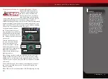
Your model is equipped with the newest TQi 2.4GHz transmitter 

with Traxxas Link

 Model Memory. The transmitter has two 

channels for controlling your throttle and steering. The receiver 
inside the model has 5 output channels. Your model is equipped 
with one servo and an electronic speed control. 

TRANSMITTER AND RECEIVER 

Steering 

Trim

Multi-Function 

Knob

Throttle 

Trigger

Steering Wheel

Power Switch

Battery Compartment

Set Button

Menu Button

Red/Green Status LED

see page 30 for more info

Link 

Button

LED

Sensor Expansion 

Port

**

** Accessory sensor expansion port for use with the Telemetry Expander Module 
     (see Traxxas.com and included materials for more information)

MODEL WIRING DIAGRAM

to Motor

LED

EZ-Set Button
(On/Off Button)

Heat Sink

VXL-3s ELECTRONIC SPEED CONTROL

Traxxas High-Current 

Connector (Male)

to Battery

Receiver cable 
(RX wire)

Cooling Fan 

Connector

(for optional use)

V/T

 - Voltage/Temp Sensor Port

RPM

 - RPM Sensor Port

BATT/

CH5

 - Battery/Channel 5*

CH4

 - Channel 4*

CH3

 - Channel 3*

CH2

 - 

Speed Control

CH1

 - 

Steering Servo

CH1

 - Channel 1* 

*Not used     

Accessory sensor ports for use with standard voltage/temperature and RPM


               telemetry sensors (see Traxxas.com and included materials for more information

Traxxas High-Current 

Connector (Male)

to Battery

Brushless Motor


(see sidebar for proper 

motor wiring)

Channel 1

Steering Servo

Channel 2

Electronic Speed Control

Cooling Fan

Connector

(for optional use)

Antenna

Motor Cap

ESC/Motor Wiring Diagram

Summary of Contents for 4-Tec 2.0

Page 1: ...MODEL 83076 4 owner s manual extreme brushless power extreme brushless power extreme brushless power system extreme brushless power system ...

Page 2: ... model Traxxas Support Traxxas support is with you every step of the way Refer to the next page to find out how to contact us and what your support options are Quick Start This manual is designed with a Quick Start path that outlines the necessary procedures to get your model up and running in the shortest time possible If you are an experienced R C enthusiast you will find it helpful and fast Be ...

Page 3: ...al assistance is also available at Traxxas com You may also e mail customer support with your question at support Traxxas com Join thousands of registered members in our online community at Traxxas com Traxxas offers a full service on site repair facility to handle any of your Traxxas service needs Maintenance and replacement parts may be purchased directly from Traxxas by phone or online at Traxx...

Page 4: ...n First Switch on your transmitter first before switching on the speed control to prevent runaways and erratic performance Don t Get Burned The ESC and motor can become extremely hot during use so be careful not to touch them until they cool Supply adequate airflow for cooling Use the Factory Installed Connectors Do not change the battery and motor connectors Improper wiring can cause fire or dama...

Page 5: ...battery packs in series or parallel Charging packs in series or parallel may result in improper charger cell recognition and an improper charging rate that may lead to overcharging cell imbalance cell damage and fire FIRE HAZARD WARNING CAUTION DANGER ALWAYS inspect your LiPo batteries carefully before charging Look for any loose leads or connectors damaged wire insulation damaged cell packaging i...

Page 6: ...uld be released If eye or skin contact occurs flush with water If a battery gets hot to the touch during the charging process temperature greater than 110 F 43 C immediately disconnect the battery from the charger and discontinue charging Allow the battery pack to cool off between runs before charging ALWAYS unplug the charger and disconnect the battery when not in use ALWAYS unplug the battery fr...

Page 7: ...n any R C toolbox Safety glasses Traxxas Ultra Premium Tire Glue Part 6468 CA glue Hobby knife Side cutters and or needle nose pliers Phillips screwdriver Soldering iron For more information on batteries see Use the Right Batteries on page 13 Various pre load spacers and shock pistons on parts tree see page 23 4 way wrench 6 or 7 cell NiMH battery pack or 2s LiPo battery pack with Traxxas High Cur...

Page 8: ...Hold Down Steering Block Caster Block Antenna Mount Receiver Box Front Suspension Arm Front Bumper Steering Servo Shock Toe Link Front Camber Link Rear Camber Link Rear Shock Tower Traxxas High Current Connector Chassis Front Adjustable Body Mount Front Shock Tower Drive Shaft Rear Suspension Arm Rear Adjustable Body Mount ...

Page 9: ...er See page 13 9 Detail your model See page 10 The transmitter requires 4 AA alkaline batteries sold separately Install wings if necessary and apply other decals if desired 4 Install battery pack in the model See page 14 10 Drive your model See page 20 Your model requires a fully charged battery pack not included Driving tips and adjustments for your model 5 Install the antenna See page 14 11 Main...

Page 10: ...ergize the electromagnetic windings in sequence to provide rotation Opposite of a brushed motor the brushless motor has its windings coils on the perimeter of the motor can and the magnets are mounted to the spinning rotor shaft Cogging Cogging is a condition sometimes associated with brushless motors Typically it is a slight stutter noticed when accelerating from a stop It happens for a very shor...

Page 11: ...adio unit that sends throttle and steering instructions to your model Trim The fine tuning adjustment of the neutral position of the servos made by adjusting the throttle and steering trim knobs on the face of the transmitter Note The Multi Function knob must be programmed to serve as a throttle trim adjustment Thermal Shutdown Protection Temperature sensing electronics used in the VXL 3s electron...

Page 12: ...Module see Traxxas com and included materials for more information MODEL WIRING DIAGRAM to Motor LED EZ Set Button On Off Button Heat Sink VXL 3s ELECTRONIC SPEED CONTROL Traxxas High Current Connector Male to Battery Receiver cable RX wire Cooling Fan Connector for optional use V T Voltage Temp Sensor Port RPM RPM Sensor Port BATT CH5 Battery Channel 5 CH4 Channel 4 CH3 Channel 3 CH2 Speed Contro...

Page 13: ...y pack installed in the model Refer to the Troubleshooting section on page 30 for more information on the transmitter status LED codes If the status LED doesn t light green check the polarity of the batteries If you see any other flashing signal from the LED refer to the chart on page 30 to identify the code Use the Right Batteries Your transmitter uses AA batteries Use new alkaline batteries Do n...

Page 14: ...ith the Traxxas High Current Connector Standard connectors restrict current flow and are not capable of delivering the power needed to maximize the output of the XL 5 The Traxxas connector s gold plated terminals with large contact surfaces ensure positive current flow with the least amount of resistance Secure long lasting and easy to grip the Traxxas connector is engineered to extract all the po...

Page 15: ...e face of the transmitter adjusts the neutral center point of the steering channel Note Traxxas Stability Management TSM must be completely turned off while adjusting steering trim See page 17 for TSM adjustments Multi Function Knob The Multi Function knob can be programmed to control a variety of functions From the factory the Multi Function knob controls Traxxas Stability Management TSM For more...

Page 16: ...nd held transmitter Range Testing the Radio System Before each running session with your model you should range test your radio system to ensure that it operates properly 1 Turn on the radio system and check its operation as described in the previous section 2 Have a friend hold the model Make sure hands and clothing are clear of the wheels and other moving parts on the model 3 Walk away from the ...

Page 17: ...stop to turn TSM completely off Note TSM is deactivated automatically when driving or braking in reverse When driving on surfaces with some traction decrease the TSM setting to allow the vehicle to feel more loose for power sliding drifting and so on On surfaces with very little traction loose dirt smooth concrete ice snow increase TSM to maximize acceleration and control Drive with TSM on and off...

Page 18: ...and the transmitter is restored to default VXL 3s Setup Programming Calibrating your ESC and transmitter Read through all of the programming steps before you begin If you get lost during programming or receive unexpected results simply unplug the battery wait a few seconds plug the battery back in and start over 1 Connect a fully charged battery pack to the VXL 3s 2 Turn on the transmitter with th...

Page 19: ... ready to drive SelectingTrainingMode Profile 3 50 Forward 100 Brakes 50 Reverse 1 Connect a fully charged battery pack to the VXL 3s and turn on your transmitter 2 With the VXL 3s off press and hold the EZ Set button until the LED turns solid green then solid red and then begins blinking red indicating the Profile numbers 3 When the LED blinks red three times release the EZ Set button 4 The LED w...

Page 20: ...f road could also cause excessive loads on the electrical system The Titan 12T motor will benefit from a short break in period to ensure optimum performance and longer motor life For the first battery pack use the stock installed pinion gear and drive smoothly on a flat paved surface Accelerate smoothly avoiding full throttle starts with most of the driving being done at higher speeds This will he...

Page 21: ...ehicle in Wet Conditions before proceeding Make sure you understand the additional maintenance required with wet running 2 The wheels have small holes molded in to allow air to enter and exit the tire during normal running Water will enter these holes and get trapped inside the tires if holes are not cut in the tires Cut two small holes 3mm or 1 8 diameter in each tire Each hole should be near the...

Page 22: ...Radio Gear The unique design of the receiver box allows the removal and installation of the receiver without losing the ability to maintain a watertight seal in the box The patent pending wire clamp feature gives you the ability to also install aftermarket radio systems and maintain the watertight features of the receiver box Removing the Receiver 1 To remove the cover remove the three 2 5x10mm so...

Page 23: ...e piston with heavier oil We recommend using the two hole pistons with a range of oil viscosities from 10W to 50W available from your hobby shop The thinner viscosity oils 30W or less flow more smoothly and are more consistent while thicker oils provide more damping Use only 100 pure silicone shock oil to prolong seal life The model s ride height can be adjusted by adding or removing the clip on s...

Page 24: ...the factory the differentials are sealed to maintain consistent long term performance Changing the oil in the differential with either lower or higher viscosity oil will vary the performance characteristics of the differentials Changing to a higher viscosity oil in the differential will reduce the tendency for motor power to be transferred to the wheel with the least traction You may notice this w...

Page 25: ... chassis 3 Remove the two 3x10mm button head screws that hold the rear body mount to the shock tower and the 3x12mm button head screw that secures the rear body mount to the differential cover 4 Remove the two 3x14mm button head screws that hold the shocks to the shock tower 5 Use a 1 5mm hex wrench to remove the two screw pins that hold the drive cups to the differential output shafts 6 Remove th...

Page 26: ... lengthen or shorten the wheelbase by up to 3mm for the perfect body fit Remove the rear suspension arms from the vehicle and trim material from the front or rear of the arms Save the material you remove and add it to the opposite side of the arms to act as a spacer or use washers to shim the arms Note The front suspension arms are not adjustable and should not be modified or trimmed High Angle St...

Page 27: ...r holes will increase camber and slightly reduce roll stiffness This modification also requires adjustable camber links part 8341X sold separately to lengthen the links and ensure proper camber settings Suspension Droop Adjustment Suspension droop is the amount of downward travel on the wheels how much the suspension arm hangs down when the chassis is off the ground Molded screw bosses in the susp...

Page 28: ...ded Steering Over time you may notice increased looseness in the steering system Replace any components as needed to restore factory tolerances Shocks Keep the oil level in the shocks full Use only 100 pure silicone shock oil to prolong the life of the seals If you are experiencing leakage around the top of the shock inspect the bladder in the top cap for signs of damage or distortion from overtig...

Page 29: ...o travel applied to steering Turning the Multi Function knob fully clockwise will deliver maximum steering throw turning the knob counterclockwise reduces steering throw note turning the dial counterclockwise to its stop will eliminate all servo travel Be aware that the steering End Point settings define the servo s maximum steering throw If you set Steering Percentage to 100 by turning the Multi ...

Page 30: ...ember the Steering Percentage setting Adjustments you make to Steering Sensitivity will be applied to the 50 steering throw setting you selected previously Likewise setting the Multi Function knob to disabled will prevent the knob from making further adjustments but the last setting of the Multi Function knob will still apply Failsafe Your Traxxas radio system is equipped with a built in failsafe ...

Page 31: ... list of model memory entries The transmitter and receiver do it all for you automatically To activate Model Lock 1 Switch on the transmitter and receiver you wish to lock 2 Press and hold MENU Release when the status LED blinks green 3 Press MENU three times The status LED will blink green four times repeatedly 4 Press SET The status LED will blink green in single flash intervals 5 Press SET once...

Page 32: ...ws how to navigate through the TQi transmitter s various settings and functions Press and hold MENU to enter the Menu Tree and use the following commands to navigate through the menu and select options MENU When you enter a menu you always start at the top Press MENU to move down the Menu Tree When you reach the bottom of the tree pressing MENU again will return you to the top SET Press SET to mov...

Page 33: ...green LED blinks Press SET red LED blinks x3 Press MENU twice red LED blinks x3 Turn steering wheel to desired max left and right travel x8 Press SET to save each position Turn steering wheel to test settings IF END POINTS ARE OK Press hold MENU returns to driving mode IF END POINTS NEED TO BE CHANGED Press SET and repeat steps 6 8 To reset the END POINTS of STEERING servo to defaults Press hold M...

Page 34: ... driving and not miss a single apex Manage up to 30 Models with Traxxas Link The TQi radio system automatically keeps track of what vehicles it has bound to and what settings were used for each up to 30 models total Traxxas Link provides a visual interface to name the models customize their settings attach profiles and lock them into memory Simply choose a model and any previously bound transmitte...

Page 35: ...TRAXXAS 35 ...

Page 36: ...6250 TRAXXAS WAY McKINNEY TEXAS 75070 1 888 TRAXXAS 200618 83076 4 OM N EN R05 extreme brushless power extreme brushless power extreme brushless power system extreme brushless power system ...

Reviews: