27
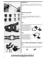
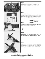
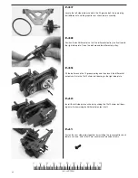
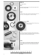
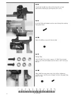
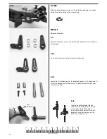
F-47
Attach the lower rear suspension arms to the side frames by inserting
the 38mm hinge pins through the pivot point. Carefully notice how the
arms are positioned in the photo. Secure the opposite end of each hinge
pin with a small E-clip.
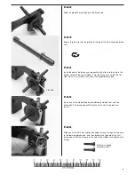
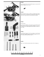
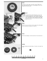
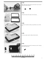
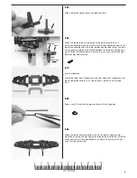
F-48
Attach the left stub axle housing to the end of the the left suspension
arm and the right stub axle housing to the right suspension arm by
inserting the 25.5mm hinge pins through the pivot points. Secure the
opposite end of each hinge pin with a small E-clip.
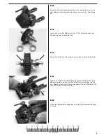
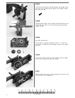
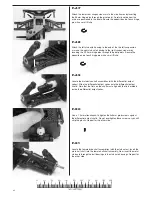
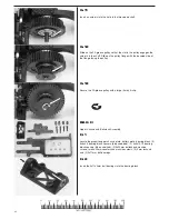
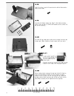
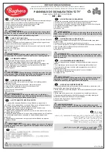
F-49
Locate the male drive shaft assemblies (with the differential output
yokes). Slide the differential output yokes onto the differential output
shafts. Note that the flats on the shaft must align with the flats molded
inside the differential output yokes.
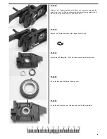
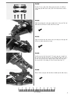
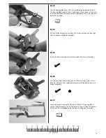
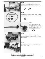
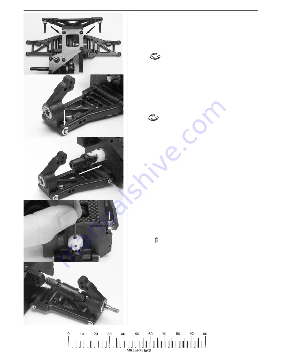
F-50
Use a 1.5mm allen wrench to tighten the 3x3mm grub screws against
the differential output shafts. Do not overtighten these screws or you will
strip the plastic. Repeat for the other side.
F-51
Locate the female driveshaft assemblies (with the stub axles). Insert the
male half shaft into the female halfshaft assembly. Now, insert the metal
stub axle through the ball bearings in the stub axle housings. Repeat for
the other side.


