36
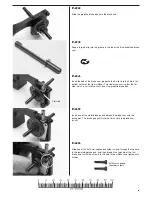
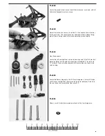
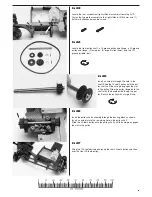
H-24
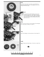
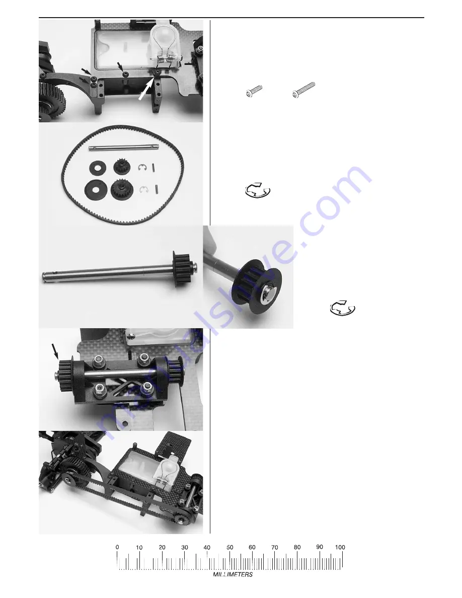
Locate the front pulley shaft, a 15-groove pulley and flange, a 20-groove
pulley and flange, (2) axle pins, (2) large E-clips (5mm), and the 121-
groove (middle) belt.
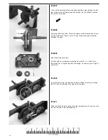
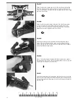
H-25
Insert an axle pin through the hole in the
shaft. Slide the 15-tooth pulley onto the pul-
ley shaft until the axle pin engages the slot
in the pulley. Slide the pulley flange onto the
shaft, with the beveled side facing the pul-
ley. Secure the pulley with a large E-clip.
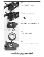
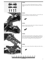
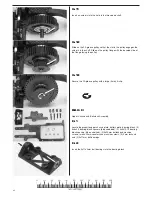
H-26
Insert the pulley shaft assembly through the bearing block as shown.
Insert an axle pin into the remaining hole in the pulley shaft.
Slide the 20-tooth pulley onto the pulley shaft until the axle pin engages
the slot in the pulley.
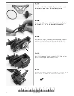
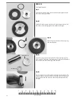
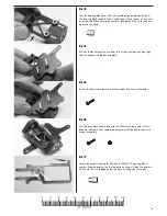
H-27
Wrap the 120-tooth drive belt around the rear 20-tooth pulley and then
over the front 20-tooth pulley.
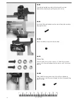
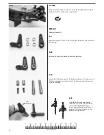
H-23
Locate the rear suspension/ right stiffener assembly from step G-12.
Fasten the top plate assembly to the right stiffener (3) 3x8mm and (1)
3x10mm buttonhead machine screws.
3x10mm

