41
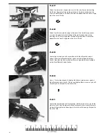
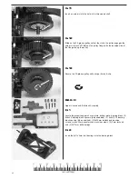
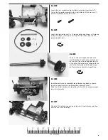
I-22
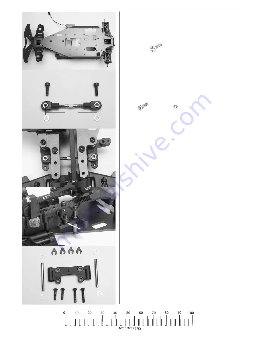
Fit the drag link through the middle of the front belt and then position it
on the bellcranks as shown. The washers insert under the hollow ball
connector on each bellcrank
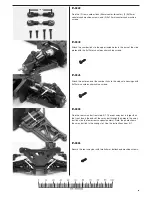
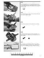
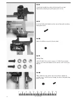
I-23
Fasten the drag link to the bellcranks with the 3x10mm caphead
machine screws and 3x6x.5mm flat metal washers. The washer inserts
between the hollow ball connector and the bellcrank (arrow).
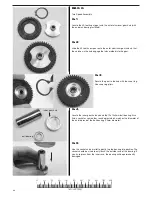
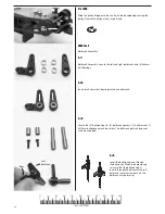
I-24
Locate the upper control arm mount, (2) 33.5mm hinge pins, (4) small e-
clips (3mm), (2) 3x12mm buttonhead machine screws, (2) 3x15mm but-
tonhead machine screws,and the upper control arms (from step C-8).
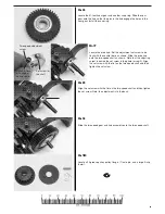
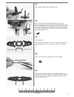
I-21
Locate the drag link from step C-5 (50mm center-to-center), (2) 3x10mm
caphead machine screws, and (2) 3x6x.5mm flat metal washers.
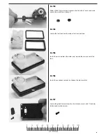
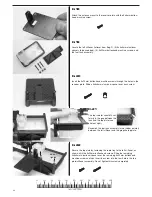
I-20
Turn the assembly over and fasten the lower chassis to the upper chas-
sis with (16) 3x10 countersunk machine screws in the locations indicat-
ed in the photo.
50mm
1
2
3
4
5
8
6
7
9
14
15
16
11
10
13
12

