background image

RAPTOR • 19

ADJUSTING THE ELECTRONIC SPEED CONTROL

8. The XL-5 is equipped with thermal shutdown protection to guard against 

overheating caused by excessive current flow. If the operating temperature 
exceeds safe limits, the XL-5 will automatically shut down. The LED on the 
face of the XL-5 will rapidly blink red, even if the throttle trigger is moved 
back and forth. Once the temperature returns to a safe level, the XL-5 will 
once again function normally. 

XL-5 Profile Selection

The speed control is factory set to Sport Mode (100% forward, brakes, and 
reverse). To disable reverse (Race Mode) or to allow 50% power (patented 
Training Mode), follow these steps. The speed control should be connected to 
the receiver and the transmitter adjusted as described previously. The profiles 
are selected by entering the programming mode.

Profile Description

Profile #1 (Sport Mode): 100% Forward, 100% Brakes, 100% Reverse
Profile #2 (Race Mode): 100% Forward, 100% Brakes, No Reverse
Profile #3 (Training Mode): 50% Forward, 100% Brakes, 50% Reverse

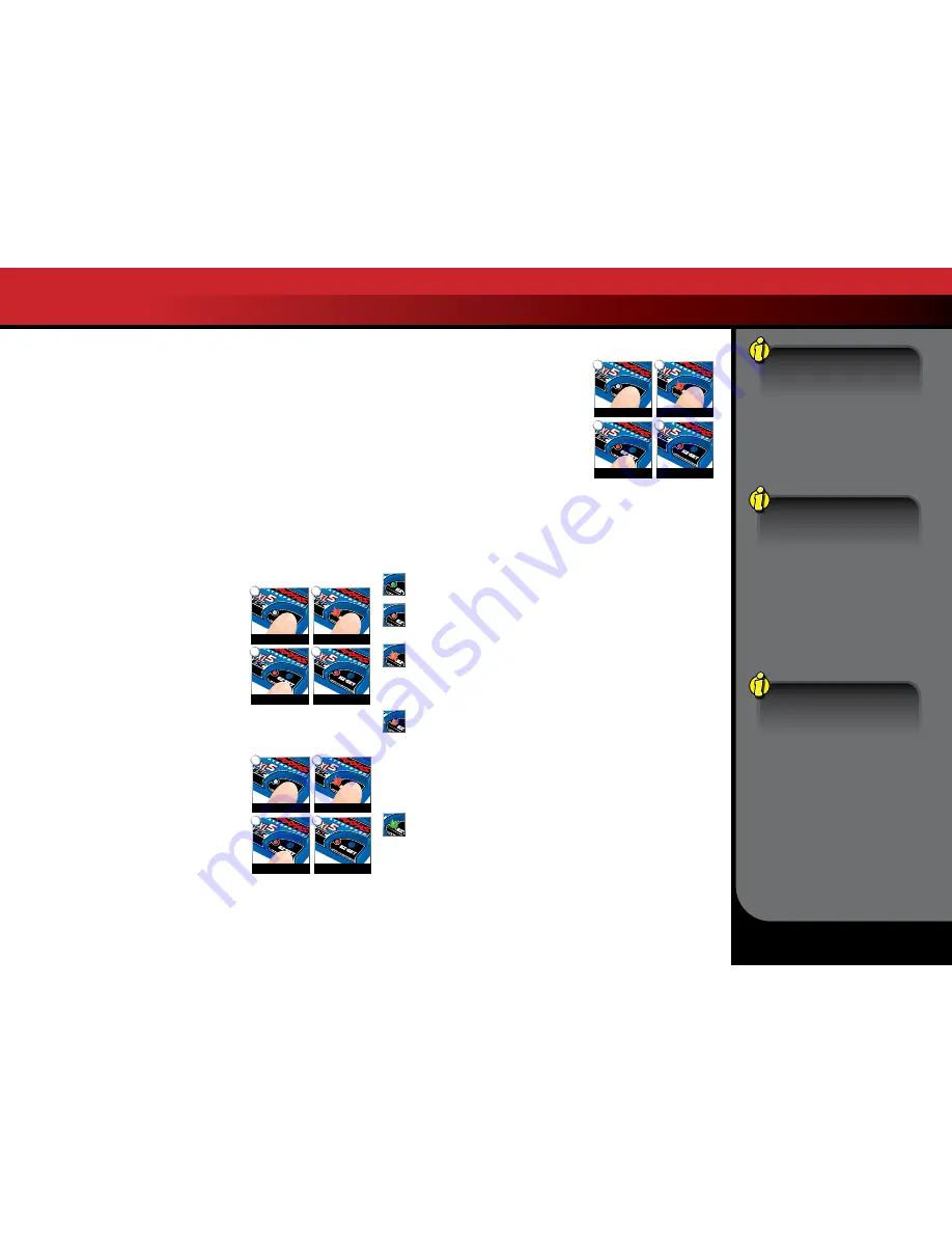
Selecting Sport Mode 

(Profile #1: 100% Forward, 100% Brakes, 100% Reverse)

1. Connect a fully charged battery pack to  

the XL-5 and turn on your transmitter.

2. With the XL-5 off, press and hold  

the EZ-Set button until the LED turns solid 
green, then solid red and then begins blinking 
red (indicating the Profile numbers).

3. When the LED blinks RED ONCE, release  

the EZ-Set button.

4. The LED will blink and then turn solid green 

(Low-Voltage Detection ACTIVE) or red (Low-Voltage Detection DISABLED). 
The model is ready to drive.

Selecting Race Mode

 (Profile #2: 100% Forward, 100% Brakes, No Reverse)

1. Connect a fully charged battery pack to  

the XL-5 and turn on your transmitter.

2. With the XL-5 off, press and hold  

the EZ-Set button until the LED turns solid 
green, then solid red and then begins blinking 
red (indicating the Profile numbers).

3. When the LED blinks RED TWICE, release  

the EZ-Set button.

4. The LED will blink and then turn solid green 

(Low-Voltage Detection ACTIVE) or red (Low-Voltage Detection DISABLED). 
The model is ready to drive.

Selecting Training Mode

 (Profile #3: 50% Forward, 100% Brakes, 50% Reverse)

1. Connect a fully charged battery pack to the 

XL-5 and turn on your transmitter.

2. With the XL-5 off, press and hold the EZ-Set 

button until the LED turns solid green, 
then solid red and then begins blinking red 
(indicating the Profile numbers).

3. When the LED blinks RED THREE  

TIMES, release the EZ-Set button.

4. The LED will blink and then turn solid green 

(Low-Voltage Detection ACTIVE) or red (Low-Voltage Detection DISABLED). 
The model is ready to drive.

Note:

 If you missed the mode you wanted, keep the EZ-Set button pressed 

down and the blink cycle will repeat until the button is released and a Mode is 
selected.

LED Codes and Protection Modes

• 

Solid Green:

 XL-5 power-on light. Low-Voltage Detection is ACTIVATED 

(LiPo setting). 

• Solid Red:

 XL-5 power-on light. Low-Voltage Detection is DISABLED  

(

NiMH setting). 

Never use LiPo batteries while Low-Voltage Detection is 

disabled.

• Fast Blinking Red:

 The XL-5 is equipped with thermal shutdown 

protection to guard against overheating caused by excessive current 
flow. If the operating temperature exceeds safe limits, the XL-5 will 
automatically shut down. Let the XL-5 cool. Make sure your model is 
properly geared for the conditions.

• 

Slow Blinking Red (when Low-Voltage Detection is activated):

 The XL-5 

has entered Low-Voltage Protection. When the battery voltage begins to 
reach the minimum recommended discharge voltage threshold for LiPo 
battery packs, the XL-5 will limit the power output to 50% throttle. When 
the battery voltage attempts to fall below the minimum threshold, the 
XL-5 will shut down all motor output. The LED on the speed control will 
slowly blink red, indicating a low-voltage shutdown. The XL-5 will stay in 
this mode until a fully charged battery is connected.

• Fast Blinking Green:

 The XL-5’s LED will blink fast green if the speed 

control is not receiving a signal. Make certain the speed control is properly 
plugged into the receiver and the transmitter is switched on.

Patented Training Mode 
(Profile #3) reduces forward 
and reverse throttle by 50%. 
Training Mode is provided 
to reduce the power output, 
allowing beginning drivers to 
better control the model. As 
driving skills improve, simply 
change to Sport or Race Mode 
for full-power operation.

Tip For Fast Mode Changes

The XL-5 is set to Profile 1 (Sport 
Mode) as the default. To quickly 
change to Profile 3 (Training 
Mode), with the transmitter on, 
press and hold the EZ-Set button 
until the light blinks red three 
times and then release. For full 
power, quickly change back 
to Profile 1 (Sport Mode)  by 
pressing and holding the EZ-Set 
button until the light blinks red 
one time and then releasing.

Recalibrating the  
XL-5 Speed Control

If the red LED on the XL-5 
speed control glows solid when 
powered on and the motor 
does not receive power when 
the throttle is applied, the 
throttle neutral position has 
changed. To restore the speed 
control to normal operation, 
it must be recalibrated to the 
current transmitter neutral 
setting. To recalibrate the 
speed control, see “XL-5 Setup 
Programming” on page 18.

B

One blink Red

A

Green to Red to Off

D

Solid

C

Release

B

Two blinks Red

A

Green to Red to Off

D

Solid

C

Release

B

Three blinks Red

A

Green to Red to Off

D

Solid

C

Release

Summary of Contents for 58094-1

Page 1: ...MODEL 58094 1 owner s manual ...

Page 2: ...the next page to find out how to contact us and what your support options are Quick Start This manual is designed with a Quick Start path that outlines the necessary procedures to get your model up and running in the shortest time possible If you are an experienced R C enthusiast you will find it helpful and fast Be sure and read through the rest of the manual to learn about important safety maint...

Page 3: ... community at Traxxas com Traxxas offers a full service on site repair facility to handle any of your Traxxas service needs Maintenance and replacement parts may be purchased directly from Traxxas by phone or online at BuyTraxxas com You can save time along with shipping and handling costs by purchasing replacement parts from your local dealer Do not hesitate to contact us with any of your product...

Page 4: ...ing with heat shrink tubing to prevent short circuits Transmitter on First Switch on your transmitter first before switching on the speed control to prevent runaways and erratic performance Use Neutrally Timed Motors For reverse use the motors must have 0 timing Modified motors with adjustable end bells timed to 0 or Johnson Mabuchi closed end bell motors are recommended Using motors with other th...

Page 5: ...series or parallel may result in improper charger cell recognition and an improper charging rate that may lead to overcharging cell imbalance cell damage and fire FIRE HAZARD WARNING CAUTION DANGER ALWAYS inspect your LiPo batteries carefully before charging Look for any loose leads or connectors damaged wire insulation damaged cell packaging impact damage fluid leaks swelling a sign of internal d...

Page 6: ...es to flame or other source of ignition Toxic materials could be released If eye or skin contact occurs flush with water If a battery gets hot to the touch during the charging process temperature greater than 110 F 43 C immediately disconnect the battery from the charger and discontinue charging Allow the battery pack to cool off between runs before charging ALWAYS unplug the charger and disconnec...

Page 7: ...ea to include in any R C toolbox Safety glasses Traxxas Ultra Premium Tire Glue Part 6468 CA glue Hobby knife Side cutters and or needle nose pliers Phillips screwdriver Soldering iron Supplied Tools and Equipment U joint wrench Pre load spacers and shock pistons Body clips and body washers 4 way wrench 2 5mm L wrench 2 0mm L wrench 1 5mm L wrench Turnbuckle wrench Foam battery pad Antenna nut wre...

Page 8: ... LED Light Pipe Battery Hold Down Receiver Box Antenna Mount Front Suspension Arm Front Bumper Steering Servo Shock Toe Link Front Camber Link Rear Camber Link Rear Shock Tower Chassis Front Body Mount Front Shock Tower Half Shaft Rear Suspension Arm Rear Body Mount Transmission Caster Block Steering Block Rear Bumper ...

Page 9: ...9 Detail your model See page 10 The receiver antenna and antenna tube must be properly installed before operating your model Apply other decals if desired 4 Install batteries in the transmitter See page 13 10 Drive your model See page 20 The transmitter requires 4 AA alkaline or rechargeable batteries sold separately Driving tips and adjustments for your model 5 Install battery pack in the model S...

Page 10: ...ise digital proportional throttle control Electronic speed controls use power more efficiently than mechanical speed controls so that the batteries run longer An electronic speed control also has circuitry that prevents loss of steering and throttle control as the batteries lose their charge Frequency band The radio frequency used by the transmitter to send signals to your model This model operate...

Page 11: ...ssure that is forcing the water through the hose 550 and 540 These numbers refer to the size of the motor 550 motors have armatures that are 30 longer than 540 motors IMPORTANT RADIO SYSTEM PRECAUTIONS Do not kink the receiver antenna wire Kinks in the antenna wire will reduce range DO NOT CUT any part of the receiver antenna wire Cutting the antenna will reduce range For maximum range always poin...

Page 12: ...h Current Connector Male to Battery XL 5 Electronic Speed Control Channel 2 Steering Servo Channel 1 Your model is equipped with the Traxxas TQ 2 4GHz transmitter The transmitter has two channels Channel one operates the steering and channel two operates the throttle The receiver inside the model has three output channels Your model is equipped with one servo and an electronic speed control TRANSM...

Page 13: ...smitter and check the status LED for a solid green light If the status LED flashes red the transmitter batteries may be weak discharged or possibly installed incorrectly Replace with new or freshly charged batteries The status LED does not indicate the charge level of the battery pack installed in the model Refer to the Troubleshooting section on page 17 for more information on the transmitter sta...

Page 14: ...ting and easy to grip the Traxxas connector is engineered to extract all the power your battery has to give RADIO SYSTEM RULES Always turn your transmitter on first and off last This procedure will help to prevent your model from receiving stray signals from another transmitter or other source and running out of control Your model has electronic fail safes to prevent this type of malfunction but t...

Page 15: ...eering reversing procedure 1 Press and hold the SET button on the transmitter for two seconds The status LED will flash green 2 Turn and hold the steering wheel to the full left or full right position it does not matter which position you choose 3 While holding the steering wheel in position press the SET button to reverse the channel 4 The channel is now reversed Confirm correct servo operation b...

Page 16: ... transmitter Range Testing the Radio System Before each running session with your model you should range test your radio system to ensure that it operates properly 1 Turn on the radio system and check its operation as described in the previous section 2 Have a friend hold the model Make sure hands and clothing are clear of the wheels and other moving parts on the model 3 Walk away from the model w...

Page 17: ...mp nut over the antenna tube and screw it onto the antenna post 4 Use the supplied tool to tighten the crimp nut on the post just until the antenna tube is securely in place Do not overtighten or crush the antenna wire against the chassis Do not bend or kink the antenna wire Do not shorten the antenna tube See the sidebar for more information TRAXXAS TQ 2 4GHz RADIO SYSTEM Antenna Tip Antenna Tube...

Page 18: ...utral 4 Press and hold the EZ Set button A The LED will first turn green and then red Release the button 5 When the LED blinks RED ONCE pull the throttle trigger to the full throttle position and hold it there B 6 When the LED blinks RED TWICE push the throttle trigger to the full reverse and hold it there C 7 When the LED blinks GREEN ONCE programming is complete The LED will then shine green or ...

Page 19: ...s ready to drive Note If you missed the mode you wanted keep the EZ Set button pressed down and the blink cycle will repeat until the button is released and a Mode is selected LED Codes and Protection Modes Solid Green XL 5 power on light Low Voltage Detection is ACTIVATED LiPo setting Solid Red XL 5 power on light Low Voltage Detection is DISABLED NiMH setting Never use LiPo batteries while Low V...

Page 20: ...petitive hard acceleration Tips for Increasing Run Time Use batteries with the highest mAh rating you can purchase Read and follow all maintenance and care instructions provided by the manufacturer of your batteries Use a high quality peak detecting charger Vary your speed The Titan12T is a fan cooled motor therefore moderate to top speed running helps reduce motor temperatures Lower your gear rat...

Page 21: ...er box during wet running This can cause long term problems with the sensitive electronics in the receiver Removing the receiver box cover during storage allows the air inside to dry This step can improve the long term reliability of the receiver It is not necessary to remove the receiver or unplug any of the wires 9 Additional Maintenance Increase your frequency of disassembly inspection and lubr...

Page 22: ...The model s ride height can be adjusted by adding or removing the clip on spring pre load spacers Adjust the ride height so that the suspension arms are slightly above being parallel to the ground Observe how the model handles in turns Proper set up will add stability and help prevent spin outs Experiment with different springs and shock oils to find what works best for your current track conditio...

Page 23: ...s equipped with a Titan 12T 550 motor The gear combination that comes stock on each model provides good overall acceleration and top speed If you want more top speed and less acceleration install the included high speed gearing more teeth If you want more acceleration and less top speed use a smaller optional not included pinion gear The included high speed gearing is intended for high speed runni...

Page 24: ...teering system There are several components that will wear out from use the servo saver Traxxas part 3744 the bellcrank bushings Traxxas part 2545 and the tie rod ends Traxxas part 2742 Replace these components as needed to restore factory tolerances Motor Every 10 15 runs remove clean and lubricate the motor Use a product such as electric motor cleaning spray to flush dirt out of the motor After ...

Page 25: ......

Page 26: ...161115 58094 1 OM EN R00 MODEL 58094 1 6250 TRAXXAS WAY McKINNEY TEXAS 75070 1 888 TRAXXAS owner s manual ...

Reviews: