background image

22 • TRAXXAS RALLY

MAINTAINING YOUR MODEL

Your model requires timely maintenance in order to stay in top running 
condition. 

The following procedures should be taken very seriously.

Frequently inspect the vehicle for obvious damage or wear. Look for:

1.   Cracked, bent, or damaged parts 
2.   Check the wheels and steering for binding. 
3.   Check the operation of the shock absorbers. 
4.   Check the wiring for any frayed wires or loose connections.
5.   Check the mounting of the receiver and servo(s) and speed control.
6.   Check the tightness of the wheel nuts with a wrench.
7.   Check the operation of the radio system, especially the condition of the batteries.
8.   Check for any loose screws in the chassis structure or suspension.
9.   Check the operation of the steering servo and ensure that it is not binding. 
10. Inspect the gears for wear, broken teeth, or debris lodged between the teeth. 
11. Check the tightness of the slipper clutch.

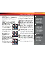
Other periodic maintenance:

• 

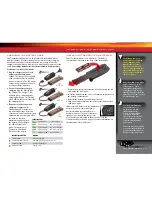
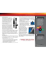
Slipper clutch pads

 (friction material): 

Under normal use, the friction 
material in the slipper clutch should 
wear very slowly. If the thickness of any 
one of the slipper clutch pads is 1.8mm or 
less, the friction disc should be replaced. Measure 
the pad thickness using calipers or measuring against the 
diameter of the 1.5 and 2.0mm hex wrenches provided with the model.

• 

Chassis

: Keep the chassis clean of accumulated dirt and grime. 

Periodically inspect the chassis for damage.

• 

Suspension

: Periodically inspect the model for signs of damage such as 

bent or dirty suspension pins, bent turnbuckles, loose screws, and any 
signs of stress or bending. Replace components as needed.

• 

Steering

: Over time, you may notice increased looseness in the steering 

system. The tie rod ends may wear out from use (Traxxas Parts #2742 and 
#5525). Replace these components as needed to restore factory tolerances. 

• 

Shocks

: Keep the oil level in the shocks full. Use only 100% pure silicon 

shock oil to prolong the life of the seals. If you are experiencing  
leakage around the top of the shock, inspect the bladder in the top cap 
for signs of damage or distortion from overtightening. If the bottom of the 
shock is leaking, then it is time for a rebuild. The Traxxas rebuild kit  
for two shocks is part #2362.  

• 

Driveline

: Inspect the driveline for signs of wear such as worn 

drive yokes, dirty axle half shafts, and any unusual noise or 
binding. If a U-joint pops apart then it is time to replace the 
part. Remove the gear cover and Inspect the spur gear for 
wear and check the tightness of set screws in the pinion gears. 
Tighten, clean, or replace components as needed.

Storage

When you are through running your model for the day, blow it off with 
compressed air or use a soft bristled paint brush to dust-off the vehicle. 
Always disconnect and remove the battery from your model whenever 
the model is stored. If your model will be stored for a long time, then also 
remove the batteries from the transmitter.

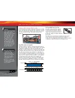
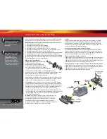
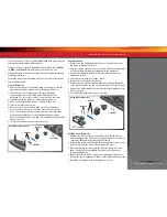
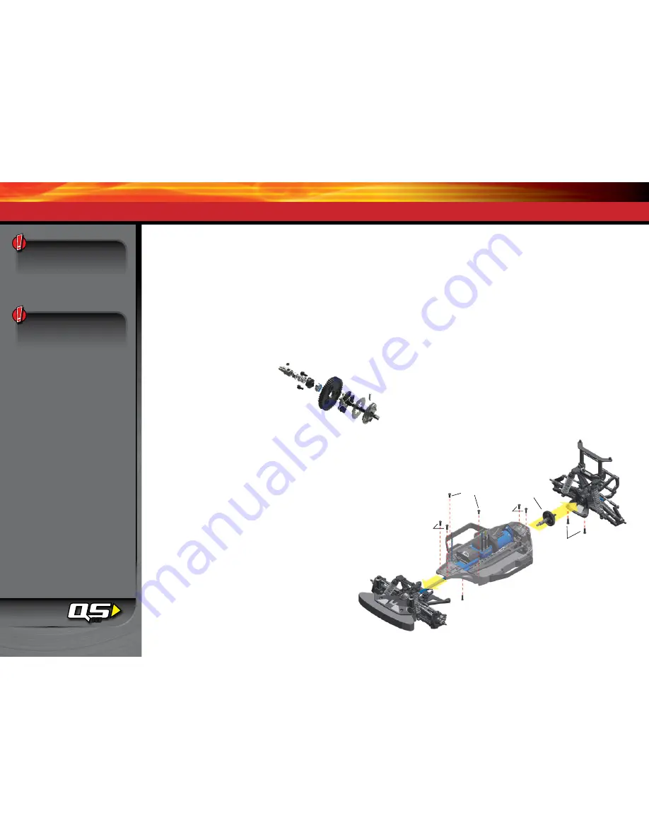
Suspension and slipper clutch assembly removal

Your model was designed with ease of disassembly in mind. The entire front 
and rear suspension assemblies can be removed from the chassis fully intact 
with the removal of only a few screws. Refer to the exploded views included in 
the Service Support Guide for complete assembly diagrams.

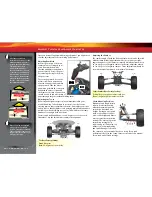
Removing the front suspension module


1. Remove the two 4x12 button-head cap screws from the front of the chassis. 
2. Remove the two 4x10 button-head cap screws from the top of the chassis. 
3. Remove the 3x15 button-head cap screw from the steering link under the chassis.  
4. Pull the front suspension assembly away from the chassis.

Removing the rear suspension module (Slipper clutch assembly removal) 

1. Remove the two 4x12 button-head cap screws from the top of the chassis. 
2. Remove the two 4x14 button-head cap screws from the bottom of the chassis. 
3. Pull the rear suspension assembly away from the chassis.
4. The slipper clutch assembly can now be removed.

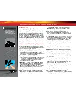
Always wear eye protection 
when using compressed 
air or spray cleaners and 
lubricants.

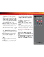
High performance vehicles 
generate small vibrations 
while driving. These 
vibrations may loosen 
hardware over time and 
require attention. Always 
check your wheel nuts and 
other hardware and tighten 
or replace when necessary.

10

4x10BCS

4x12BCS

4x12BCS

4x14BCS

3x15BCS

Rear Suspension 

Assembly

Front Suspension 

Assembly

Slipper Clutch 

Assembly

Summary of Contents for 74076 Rally

Page 1: ...owner s manual MODEL 74076 1...

Page 2: ...ce and this device must accept any interference including interference that may cause undesired operation of the device Radio Frequency RF Exposure Statement This equipment complies with radio frequen...

Page 3: ...SAFETY PRECAUTIONS All of us at Traxxas want you to safely enjoy your new model Operate your model sensibly and with care and it will be exciting safe and fun for you and those around you Failure to...

Page 4: ...ar you ask your local hobby dealer or visit www call2recycle org LiPo Batteries Lithium Polymer LiPo batteries are becoming popular for use in R C models due to their compact size high energy density...

Page 5: ...e Side cutters and or needle nose pliers Philips screwdriver Soldering iron For more information on batteries see Use the Right Batteries on page 11 U joint wrench Pre load spacers and shock pistons B...

Page 6: ...wn Caster Block Steering Block Battery Receiver Box Antenna Mount Front Suspension Arm Front Bumper Steering Servo Shock Toe Link Front Camber Link Rear Camber Link Rear Shock Tower Traxxas High Curre...

Page 7: ...nce from outside sources 3 Install batteries in the transmitter See page 11 8 Detail your model See sidebar page 8 The transmitter requires 4 AA alkaline batteries sold separately Apply other decals i...

Page 8: ...mutator and brush arrangement with intelligent electronics that energize the electromagnetic windings in sequence to provide rotation Opposite of a brushed motor the brushless motor has its windings c...

Page 9: ...r easy wire replacement The Velineon 3500 is equipped with solder tabs Transmitter The hand held radio unit that sends throttle and steering instructions to your model Trim The fine tuning adjustment...

Page 10: ...Multi Function Knob Throttle Trigger Throttle Neutral Adjust Steering Wheel Power Switch Battery Compartment Set Button Menu Button Red Green Status LED see page 27 for more info Link Button LED Sens...

Page 11: ...entation as indicated in the battery compartment 3 Reinstall the battery door and snap it closed 4 Turn on the transmitter and check the status indicator for a solid green light If the status LED flas...

Page 12: ...se it on the opposite side of the chassis Note For taller batteries an extended battery hold down part 7426X is available sold separately For shorter batteries 6 cell use the included foam block in th...

Page 13: ...he transmitter and start over Always turn on the transmitter before plugging in the battery RADIO SYSTEM BASIC ADJUSTMENTS Throttle Neutral Adjustment The throttle neutral adjustment is located on the...

Page 14: ...t apply full throttle in forward or reverse while the model is elevated 8 Once adjustments are made turn off the receiver on your model followed by the hand held transmitter Range Testing the Radio Sy...

Page 15: ...Multi Function knob clockwise the steering sensitivity of the model will be decreased Note that a relatively large amount of steering wheel travel results in a smaller amount of servo travel The fart...

Page 16: ...ck to the factory defaults Otherwise you may not get the best performance from your speed control The transmitter should be adjusted as follows If the transmitter setting have been adjusted reset them...

Page 17: ...to drive SelectingTrainingMode Profile 3 50 Forward 100 Brakes 50 Reverse 1 Connect a fully charged battery pack to the VXL 3s and turn on your transmitter 2 With the VXL 3s off press and hold the EZ...

Page 18: ...charger Read and follow all maintenance and care instructions provided by the manufacturer of your batteries and charger Keep the VXL 3s cool Get plenty of airflow across the ESC heat sinks Use the co...

Page 19: ...electronics in the receiver Removing the receiver box cover during storage allows the air inside to dry This step can improve the long term reliability of the receiver It is not necessary to remove th...

Page 20: ...ately Adjust the front wheels to 1 to 2 degrees of negative camber In the rear adjust the wheels to 1 to 2 degrees of negative camber These adjustments should be set with the model positioned at its n...

Page 21: ...nob to the center 0 position 5 Disconnect motor wires A and C see page 10 to prevent the motor from turning during the next steps Connect a fresh battery pack to the speed control and turn on the ESC...

Page 22: ...rtion from overtightening If the bottom of the shock is leaking then it is time for a rebuild The Traxxas rebuild kit for two shocks is part 2362 Driveline Inspect the driveline for signs of wear such...

Page 23: ...t hole Position 1 or 2 Position 4 is the stock setting To lower the roll center further move the outer camber link ends to the lower position on the C hub Bump steer correction Bump steer refers to un...

Page 24: ...n high current motor applications TUNING THE SEALED GEAR DIFFERENTIALS The action of the model s front and rear gear differentials can be tuned for different driving conditions and performance require...

Page 25: ...ial 1 Remove the two 3x20mm button head screws that secure the top bumper mount to diff case 2 Turn the chassis over and remove the two 3x12mm countersunk screws that hold the bumper skid plate to the...

Page 26: ...ustment settings you select will represent what you wish to be the servo s maximum travel the Steering Percentage or Braking Percentage functions will not override the End Point settings Steering and...

Page 27: ...u may wish to delete a model you no longer drive from the memory 1 Switch on the transmitter and receiver you wish to delete 2 Press and hold MENU Release when the status LED blinks green 3 Press MENU...

Page 28: ...Push forward to desired endpoint and press set to save To reset max throw Let go of controls and press SET The menu tree below shows how to navigate through the TQi transmitter s various settings and...

Page 29: ...LED blinks Press SET red LED blinks x3 Press MENU twice red LED blinks x3 Turn steering wheel to desired max left and right travel x8 Press SET to save each position Turn steering wheel to test settin...

Page 30: ...threshold warnings and log maximums minimums or averages Use the recording function to document your dashboard view with sound so that you can keep your eyes on your driving and not miss a single apex...

Page 31: ...____ wt Oil __________ wt Piston 1 hole Piston 1 hole Piston 2 hole Piston 2 hole Piston 3 hole Piston 3 hole Battery Placement Front Tire Type_________________ Tire Insert_ _______________ Wheel_ ___...

Page 32: ...______lbs Springs Color ___________________ Preload _________mm ______mm ______mm Springs Color ___________________ Preload _________mm Oil __________ wt Oil __________ wt Piston 1 hole Piston 1 hole...

Page 33: ..._mm Oil __________ wt Oil __________ wt Piston 1 hole Piston 1 hole Piston 2 hole Piston 2 hole Piston 3 hole Piston 3 hole Battery Placement Front Tire Type_________________ Tire Insert_ ____________...

Page 34: ...6200 TRAXXAS WAY McKINNEY TEXAS 75070 1 888 TRAXXAS 141231 74076 1 OM N EN R01...

Reviews: