background image

TRAXXAS • 17

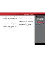
to see and control the model. Most drivers will struggle to see and 
drive their model at distances farther than a football field (300+ 
feet). At greater distances, you could lose sight of your model and 
you may also exceed the radio system’s operating range which will 
cause the fail-safe system to activate. For best visibility and control 
of your model keep your model within 200 feet, regardless of the 
maximum range available.

No matter how fast or far you drive your model, always leave 
adequate space between you, the model, and others. Never drive 
directly toward yourself or others. 

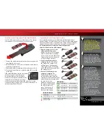
TQ 2.4GHz Binding Instructions

For proper operation, the transmitter and receiver must be electronically 
‘bound.’

 This has been done for you at the factory. 

Should you ever 

need to re-bind the system or bind to an additional transmitter or 
receiver, follow these instructions. 

Note

: the receiver must be connected 

to a 4.8-6.0v (nominal) power source for binding and the transmitter and 
receiver must be within 5 feet of each other.

1. Press and hold the SET button on the transmitter.

2. Turn on the transmitter and release the SET button. The status LED will 

flash red slowly, indicating that the transmitter is in bind mode. 

3. Press and hold the LINK button on the receiver.

4. Turn on the speed control by pressing the EZ-Set button and release 

the LINK button.

5. When the LEDs on both the transmitter and the receiver turn solid 

green, the system is bound and ready for use. Confirm that the 
steering and throttle operate properly before driving your model.

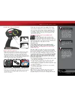
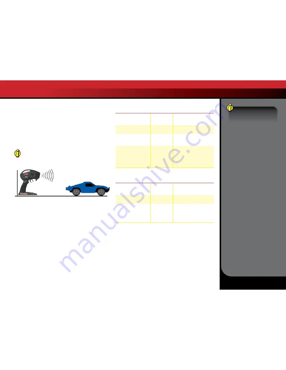
The TQ 2.4GHz transmitter has a directional antenna. For 
maximum range, hold the antenna upright and pointed in 
the direction of the model. Pointing the transmitter away 
from the model will reduce radio range.

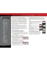
TRANSMITTER LED CODES

LED Color / Pattern

Name

Notes

Solid green

Normal Driving 
Mode

See page 15 for information 
on how to use the transmitter 
controls.

Slow red  
(0.5 sec on / 0.5 sec off) 

Binding

See this page for more information 
on binding.

Flashing medium red
(0.25 sec on / 0.25 sec off)

Low Battery 
Alarm

Put new batteries in the 
transmitter. See page 13 for 
more information.

Flashing fast red 
(0.125 sec on / 0.125 sec off)

Link Failure / 
Error

Transmitter and receiver are no 
longer bound. Turn the system 
off and then back on to resume 
normal operation. Find source of 
the link failure (i.e., out of range, 
low batteries, damaged antenna).

RECEIVER LED CODES

LED Color / Pattern

Name

Notes

Solid green

Normal Driving 
Mode

See page 15 for information 
on how to use your transmitter 
controls.

Slow red  
(0.5 sec on / 0.5 sec off) 

Binding  

See this page for more information 
on binding.

Flashing fast red  
(0.125 sec on / 0.125 sec off)

Fail-Safe / Low-
Voltage Detect

Consistent low voltage in the 
receiver triggers Fail-Safe so 
that there is enough power to 
center the throttle servo before it 
completely loses power.

Fail-Safe

Your Traxxas radio system 
is equipped with a built-
in fail-safe function that 
returns the throttle to its 
last saved neutral position 
in the event of a signal loss. 
The LED on the transmitter 
and the receiver will rapidly 
flash red when the fail-
safe mode is activated. If 
fail-safe activates while you 
are operating your model, 
determine the reason for 
signal loss and resolve the 
problem before operating 
your model again.

TRAXXAS TQ 2.4GHz RADIO SYSTEM

Summary of Contents for Bandit 24054

Page 1: ...owner s manual MODELS 36054 1 MODELS 37054 1 MODEL 24054 1...

Page 2: ...model Traxxas Support Traxxas support is with you every step of the way Refer to the next page to find out how to contact us and what your support options are Quick Start This manual is designed with...

Page 3: ...Your model is very fast and could cause injury if allowed to collide with anyone Because your model is controlled by radio it is subject to radio interference from many sources that are beyond your co...

Page 4: ...oth carpet or on any other flammable material Do not operate the charger in a cluttered space or place objects on top of the charger or battery If a battery gets hot to the touch during the charging p...

Page 5: ...s Ultra Premium Tire Glue Part 6468 CA glue Hobby knife Side cutters and or needle nose pliers Phillips screwdriver Soldering iron For more information on batteries see Use the Right Batteries on page...

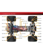
Page 6: ...Battery Battery Hold Down Upper Chassis Plate Antenna Mount Suspension Arm Front Front Body Mount Front Bumper Front Shock Tower Steering Servo under Upper Chassis Plate Shock Oil Damper Turnbuckle Ti...

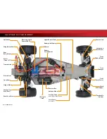
Page 7: ...eed Control XL 5 Chassis Battery Compartment Battery Hold Down Receiver Box Front Body Mount Antenna Mount Camber Link Suspension Arm Front Bulkhead Front Bumper Front Shock Tower Steering Servo Shock...

Page 8: ...Shock Tower Shock Oil Damper Turnbuckle Tie Rod Rear Shock Tower Rear Body Mount Camber Link ANATOMY OF THE BANDIT Half Shaft Suspension Arm Rear LED Light Pipe Electronic Speed Control XL 5 Battery C...

Page 9: ...tely Follow these critical steps to maintain the performance of your model and keep it in excellent running condition 4 Install battery pack in the model See page 14 Your model requires a fully charge...

Page 10: ...recise digital proportional throttle control Electronic speed controls use power more efficiently than mechanical speed controls so that the batteries run longer An electronic speed control also has c...

Page 11: ...he hose voltage corresponds to the pressure that is forcing the water through the hose 550 and 540 These numbers refer to the size of the motor 550 motors have armatures that are 30 longer than 540 mo...

Page 12: ...electronic speed control TRANSMITTER AND RECEIVER Steering Trim Throttle Trigger Steering Wheel Power Switch Battery Compartment Set Button Red Green Status LED Traxxas High Current Connector Male to...

Page 13: ...mitter and check the status LED for a solid green light If the status LED flashes red the transmitter batteries may be weak discharged or possibly installed incorrectly Replace with new or freshly cha...

Page 14: ...nd antenna tube 1 Slide the antenna wire into the antenna tube to its full extent When fully inserted the wire should reach to approximately 1 2 inch below the tube cap Do not leave any slack in the a...

Page 15: ...until the model drives straight when the steering wheel is centered Channel Reversing The TQ 2 4GHz transmitter has been programmed with the correct servo direction settings for your model and should...

Page 16: ...ooking down at the model the front wheels should be pointing straight ahead If the wheels are turned slightly to the left or right slowly adjust the steering trim control on the transmitter until they...

Page 17: ...4GHz transmitter has a directional antenna For maximum range hold the antenna upright and pointed in the direction of the model Pointing the transmitter away from the model will reduce radio range TRA...

Page 18: ...ction is now ACTIVATED To disable Low Voltage Detection NiMH setting 1 Make sure the LED on the XL 5 is on and GREEN 2 Press and hold the EZ Set button the LED will turn off After ten seconds the moto...

Page 19: ...Use caution to avoid slamming the speed control from reverse to forward On high traction surfaces this could result in transmission or driveline damage 7 To turn the XL 5 off press and hold the EZ Set...

Page 20: ...g temperature exceeds safe limits the XL 5 will automatically shut down Let the XL 5 cool Make sure your model is properly geared for the conditions Slow Blinking Red when Low Voltage Detection is act...

Page 21: ...in the model The Titan 12T motor will benefit from a short break in period to ensure optimum performance and longer motor life For the first battery pack use the stock installed pinion gear and drive...

Page 22: ...hicle in Wet Conditions before proceeding Make sure you understand the additional maintenance required with wet running 2 The wheels have small holes molded in to allow air to enter and exit the tire...

Page 23: ...re to wear eye protection when using spray aerosol cleaners RECEIVER BOX MAINTAINING A WATERTIGHT SEAL Removing and Installing Radio Gear The unique design of the receiver box allows the removal and i...

Page 24: ...pistons springs or oil always make changes to them in pairs front or rear Piston selection depends on the range of oil viscosities that you have available For example using a two hole piston with a li...

Page 25: ...eeth x 2 72 Final Gear Ratio Pinion Gear Teeth Stampede Rustler Bandit Fast Acceleration Short Distances Small Tracks 14 Tooth Pinion 90 Tooth Spur 14 Tooth Pinion 90 Tooth Spur 19 Tooth Pinion 86 Too...

Page 26: ...or cleaning it must be re centered prior to installation in the model 1 Disconnect the servo horn from the steering servo 2 Connect the steering servo to channel 1 on the receiver Connect the electron...

Page 27: ...nd Bandit only Replace these components as needed to restore factory tolerances The bell crank bushings may be replaced with 5x8mm ball bearings See the parts list included with your model for replace...

Page 28: ...6200 TRAXXAS WAY McKINNEY TEXAS 75070 1 888 TRAXXAS 140929 24054 36054 37054 1 OM N EN R00 owner s manual...

Reviews: