background image

TR A X X AS • 21

Before Running Your Vehicle in Wet Conditions

1.  Consult the section “After Running Your Vehicle in Wet Conditions” before 

proceeding.  Make sure you understand the additional maintenance required 
with wet running.

2.  The wheels have small holes molded in to allow air to enter and exit the tire 

during normal running. Water will enter these holes and get trapped inside the 
tires if holes are not cut in the tires. Cut two small holes (3mm or 1/8” diameter) 
in each tire.  Each hole should be near the tire centerline, 180 degrees apart. 

3.  Confirm that the RX box O-ring and cover are installed correctly and secure. 

Make sure the screws are tight and the blue O-ring is not visible protruding 
from the edge of the cover.

4.  Confirm that your batteries can be used in wet conditions.
5.  Use lower gearing (smaller pinion gears, as low as 12T or spur gear as large as 

90T) when running in mud, deep puddles, snow, or other similar situations that 
will restrict the tires and put much higher loads on the motor. 

Motor Precautions

• Velineon motor life can be greatly reduced in mud and water. If the motor gets 

excessively wet or submerged, use very light throttle (run the motor slowly) until 
the excess water can run out. Applying full throttle to a motor full of water can 
cause rapid motor failure. Your driving habits will determine motor life with a 
wet motor. Do not submerge the motor under water.

• Do not gear the motor by temperature when running in wet conditions.  The 

motor will be cooled by water contact and will not give an accurate indication of 
appropriate gearing.

After Running Your Vehicle in Wet Conditions

1.  Drain the tires by spinning the tires at high speed to “sling” the water out. One way 

to do this is to make several high-speed passes on a flat, dry surface, if possible.

2.  Remove the batteries.
3.  Rinse excess dirt and mud off the truck with low-pressure water, such as from a 

garden hose.  Do NOT use pressure washer or other high-pressure water. Avoid 
directing water into the bearings, transmission, etc.

4.  Blow off the truck with compressed air (optional, but recommended). Wear 

safety glasses when using compressed air. 

5.  Remove the wheels from the truck.
6.  Spray all the bearings, drivetrain, and fasteners with WD-40

®

 or similar water 

displacing light oil.

7.  Let the truck stand or you may blow off with compressed air. Placing the truck 

in a warm sunny spot will aid drying. Trapped water and oil will continue to 
drip from the truck for a few hours. Place it on a towel or piece of cardboard to 
protect the surface underneath. 

8.  As a precautionary step, remove the sealed receiver box cover. While unlikely, 

humidity or tiny amounts of moisture or condensation may enter the receiver 
box during wet running.  This can cause long-term problems with the sensitive 
electronics in the receiver.  Removing the receiver box cover during storage 
allows the air inside to dry. This step can improve the long-term reliability of the 
receiver. It is not necessary to remove the receiver or unplug any of the wires.

9. 

Additional Maintenance

: Increase your frequency of disassembly, inspection 

and lubrication of the following items:  This is necessary after extended wet 
use or if the vehicle will not be used for an extended period of time (such as a 
week or longer). This additional maintenance is needed to prevent any trapped 
moisture from corroding internal steel components.

• 

Stub axle housing bearings

: Remove, clean, and re-oil the bearings.

• 

Transmission

: Remove, disassemble, clean, and re-grease the transmission 

components. Use a light coating of wheel bearing grease (from an auto parts 
store) on the metal gear teeth. Refer to your exploded view diagrams for help 
with disassembly and reassembly.

• 

Velineon motor

: Remove the motor, clean with aerosol motor cleaner, and 

re-oil the bearings with lightweight motor oil. Be sure to wear eye protection 
when using spray aerosol cleaners.

RECEIVER BOX: MAINTAINING A WATERTIGHT SEAL

Removing and Installing Radio Gear

The unique design of the receiver box allows the removal and installation of the 
receiver without losing the ability to maintain a watertight seal in the box. The 
patent-pending wire clamp feature gives you the ability to also install aftermarket 
radio systems and maintain the watertight features of the receiver box.

Removing the Receiver

1.  Remove the wire clamp by removing the two 2.5x8mm cap screws.
2.  Remove the cover by removing the two 3x10mm cap screws.
3.  To remove the receiver from the box simply lift it out and set to the side.  

The antenna wire is still inside the clamp area and cannot be removed yet.

4.  Unplug the servo cables from the receiver and remove  

the receiver.

Receiver Installation

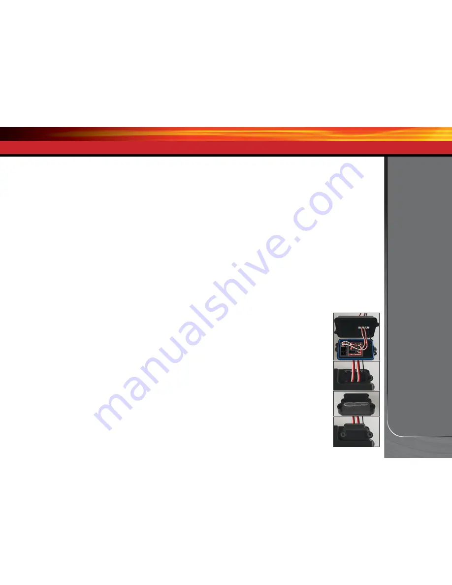
1.  Install the electronic speed control (ESC), servo, and 

antenna wiring through the receiver box top (A). Make 
sure the box light pipe is aligned with the receiver LED.

2.  Plug ESC and servo wires into the receiver (see page 12). 
3.  Bundle wiring as necessary. 
4.  Make sure the O-ring is properly seated into the groove in 

the receiver box bottom so that the cover will not pinch it 
or damage it in any way. 

5.  Place receiver box top onto receiver box bottom and  

install and tighten the two 3x10mm cap screws securely. 

6.  Inspect the cover to make sure that the O-ring seal is not visible. 
7.  Arrange the wires neatly using the wire guides on the 

receiver box top (B). Excess ESC and servo wiring should 
be bundled inside the receiver box.  Pull out all available 
antenna wiring from the receiver box. 

8.  Apply a small bead of silicone grease to the foam on the  

wire clamp (C). 

9.  Install the wire clamp and tighten the two 2.5x8mm cap 

screws securely (D).

DRIVING YOUR MODEL

A

B

C

D

Summary of Contents for Bandit VXL 24076

Page 1: ...owners manual MODEL 24076 1 extreme brushless power system MODEL 36076 1 MODEL 37076 1...

Page 2: ...e necessary procedures to get your model up and running in the shortest time possible If you are an experienced R C enthusiast you will find it helpful and fast Be sure and read through the rest of th...

Page 3: ...s operation can conflict with or disrupt pedestrian or vehicular traffic Never under any circumstances operate the model in crowds of people Your model is very fast and could cause injury if allowed t...

Page 4: ...does not recommend that anyone under the age of 14 use or handle LiPo battery packs without the supervision of a knowledgeable and responsible adult Your model is able to use LiPo batteries with nomi...

Page 5: ...nife Side cutters and or needle nose pliers Philips screwdriver Soldering iron For more information on batteries see Use the Right Batteries on page 13 U joint wrench Supplied Tools and Equipment 4 AA...

Page 6: ...pper Chassis Plate Antenna Mount Suspension Arm Front Front Body Mount Front Bumper Front Shock Tower Steering Servo under Upper Chassis Plate Shock Oil Damper Turnbuckle Toe Link Rear Shock Tower Rea...

Page 7: ...ount Suspension Arm Front Bulkhead Front Bumper Front Shock Tower Steering Servo Shock Oil Damper Turnbuckle Toe Link ANATOMY OF THE STAMPEDE VXL Suspension Arm Rear Wheelie Bar Turnbuckle Rear Camber...

Page 8: ...Suspension Arm Front Front Body Mount Front Bumper Front Shock Tower Steering Servo under Upper Chassis Plate Shock Oil Damper Turnbuckle Toe Link Rear Shock Tower Rear Body Mount Chassis Turnbuckle F...

Page 9: ...The transmitter requires 4 AA alkaline batteries sold separately Follow these critical steps to maintain the performance of your model and keep it in excellent running condition 4 Install the battery...

Page 10: ...commutator and brush arrangement with intelligent electronics that energize the electromagnetic windings in sequence to provide rotation Opposite of a brushed motor the brushless motor has its winding...

Page 11: ...easy wire replacement The Velineon 3500 is equipped with solder tabs Transmitter The hand held radio unit that sends throttle and steering instructions to your model Trim The fine tuning adjustment o...

Page 12: ...ee page 27 for more info Link Button LED Sensor Expansion Port TRAXXAS TQi RADIO VELINEON Power SYSTEM V T Voltage Temp Senor Port RPM RPM Sensor Port BATT CH5 Battery Channel 5 CH4 Channel 4 CH3 Chan...

Page 13: ...Reinstall the battery door and snap it closed 4 Turn on the transmitter and check the status indicator for a solid green light If the status LED flashes red the transmitter batteries may be weak disch...

Page 14: ...nals with a large contact surfaces ensure positive current flow with the least amount of resistance Secure long lasting and easy to grip the Traxxas connector is engineered to extract all the power yo...

Page 15: ...sition turn the transmitter off before adjusting the neutral position You will need to reprogram your electronic speed control to recognize the 70 30 setting Turn to ESC Setup Programming on page 18 f...

Page 16: ...your radio system to ensure that it operates properly 1 Turn on the radio system and check its operation as described in the previous section 2 Have a friend hold the model Make sure hands and clothi...

Page 17: ...ed for illustrative purposes Decreased Steering Sensitivity Negative Exponential By turning the Multi Function knob clockwise the steering sensitivity of the model will be decreased Note that a relati...

Page 18: ...as follows If the transmitter setting have been adjusted reset them to the factory defaults 1 Turn transmitter off 2 Hold both MENU and SET 3 Turn transmitter on 4 Release MENU and SET The transmitter...

Page 19: ...o drive SelectingTrainingMode Profile 3 50 Forward 100 Brakes 50 Reverse 1 Connect a fully charged battery pack to the VXL 3s and turn on your transmitter 2 With the VXL 3s off press and hold the EZ S...

Page 20: ...ase Use a high quality peak detecting charger Read and follow all maintenance and care instructions provided by the manufacturer of your batteries and charger Use the correct Low Voltage Detection set...

Page 21: ...ng wet running This can cause long term problems with the sensitive electronics in the receiver Removing the receiver box cover during storage allows the air inside to dry This step can improve the lo...

Page 22: ...th heavier oil We recommend using the two hole pistons with a range of oil viscosities from 10W to 50W available from your hobby shop The thinner viscosity oils 30W or less flow more smoothly and are...

Page 23: ...center of the chassis and be perpendicular to the servo body 7 Check servo operation by turning the steering wheel back and forth to ensure that the mechanism has been centered properly and you have...

Page 24: ...erances The bell crank bushings may be replaced with 5x8mm ball bearings See the parts list included with your model for replacement part number Shocks Keep the oil level in the shocks full Use only 1...

Page 25: ...ptional large pinion gear is intended for high speed running on hard surfaces and this gearing is not recommended for off road or repetitive starting and stopping LiPo Batteries LiPo batteries are int...

Page 26: ...resent what you wish to be the servo s maximum travel the Steering Percentage or Braking Percentage functions will not override the End Point settings Steering and Throttle Sub Trim The Sub Trim funct...

Page 27: ...reen four times repeatedly 4 Press SET once The status LED will blink green once repeatedly 5 Press MENU once The status LED will blink green twice repeatedly 6 Press SET The memory is now selected to...

Page 28: ...dpoint and press set to save To reset max throw Let go of controls and press SET The menu tree below shows how to navigate through the TQi transmitter s various settings and functions Press and hold M...

Page 29: ...T green LED blinks Press SET red LED blinks x3 Press MENU twice red LED blinks x3 Turn steering wheel to desired max left and right travel x8 Press SET to save each position Turn steering wheel to tes...

Page 30: ...og maximums minimums or averages Use the recording function to document your dashboard view with sound so that you can keep your eyes on your driving and not miss a single apex Manage up to 30 Models...

Page 31: ...6200 Traxxas Way McKinney TX 75070 1 888 TRAXXAS 140925 24076 36076 37076 1 OM N EN R00...

Reviews: