32 • JATO 3.3
BASIC TUNING ADJUSTMENTS
2. Set the steering trim on the transmitter to neutral (zero).
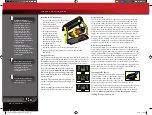
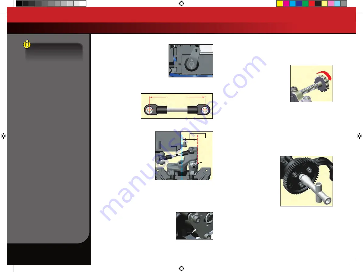
3. Position the Jato so it is level and you
can view the installed steering servo
from the front.
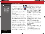
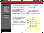
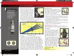
4. Verify that the servo horn is positioned
so the arrow inscribed on the face points
straight up (see illustration).
5. If it is not, remove the servo horn (by removing the 3x6mm screw),
rotate it to the correct angle, (arrow pointing up), and reinstall.
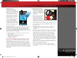
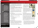
The steering servo link
must be assembled as
shown in the illustration
to the right. Note that the
rod end on one end of
the steering link is rotated
45 degrees compared the
other rod end. The exact
center-to-center distance between
the hollow balls is 43.1mm.
When the steering link is installed
in the Jato, the edge of the left
bellcrank (servo saver arm) should
be parallel to the centerline of the
vehicle (see illustration). If it is not
parallel, adjust the length of the
steering link.
BRAKE SETUP & ADJUSTMENT
Jato is equipped with an adjustable disc brake. The brake is preset at the
factory and should not require attention. As the brake material wears,
future adjustments may be necessary.
Brake Shoulder Screw Adjustment
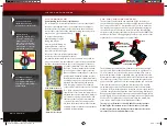
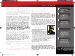
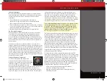
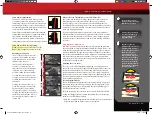
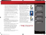
The two shoulder bolts that are used to secure
the brake pads to the transmission housing
may need to be adjusted periodically as the
brake material wears down. They should be
tightened so an approximate 0.5mm (.020”)
gap exists between the disc and the brake pad
(on the transmission side). Adjust the brake by
first pushing the outer brake pad firmly against the inner pad with your
finger, sandwiching the brake disc between the brake calipers. Tighten
the brake shoulder bolts until they just barely touch the brake pads. Do
not over tighten these fasteners or you may damage the brake disc or
pads. Loosen each of the shoulder bolts by 1 turn.
Brake Linkage Adjustment
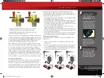
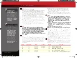
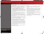
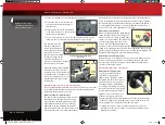
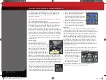
When correctly adjusted, the brake linkage
spring should barely touch the rod guide
when the servo is in neutral position (radio
system on, closed throttle). This will ensure
no brake drag during operation of the
vehicle. The brake adjustment knob can
be turned counter clockwise away from the
spring for less braking power if desired. Do not adjust the knob to apply
pressure against the spring while the servo is in the neutral position. This
will induce brake drag and cause undesirable handling.
Brake Pad Wear and Replacement
During normal use, the brake disc wears at a slow rate. If the disc wears
down to about 1.8mm in thickness, it should be replaced. Any more
wear than this could cause damage to the brake parts and improper
operation of the brake system.
TRANSMISSION TUNING
Adjusting the Slipper Clutch
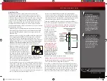
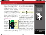
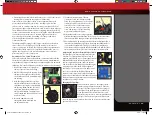
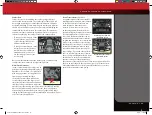
Your Jato is equipped with an
adjustable Torque Control
™
slipper clutch. The slipper clutch is
integrated into the main spur gear
on the transmission (see page 6).
The slipper clutch is adjusted by
loosening or tightening the spring-
loaded locknut on the slipper shaft.
Use the supplied 4-way wrench. To
tighten or loosen the slipper nut,
hold the spur gear to prevent it
from turning and turn the adjustment nut. Turn the adjustment nut
clockwise to tighten (less slippage) and counter-clockwise to loosen
(more slippage). The slipper clutch has two functions:
1. Limiting the engine’s torque output to the wheels to prevent
wheelspin on low-traction surfaces and uncontrolled wheelies on
high-traction surfaces.
Steering Link Length Template
(actual size)
43.1mm
Servo
Saver
Arm
Steering
Link
Parallel
Less Brake
Brake
Linkage
Spring
.5mm
gap
Optional servo horns are
available separately for use
with non-Traxxas servos.
55077-KC2104-R00-Jato-33-Owners.indd 32
6/6/14 11:53 AM

