5
PREPARING TO RUN
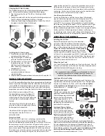
Charging the EZ-Start
®
battery
The included charger can be used to charge the included battery
pack. Do not leave the battery unattended while charging.
1.
Plug the charger into the wall. The LED on the charger should
glow green.
2.
Connect the included EZ-Start battery pack to the charger output cord.
The LED will glow red indicating the battery is charging.
3.
The battery should charge for approximately 4 ½ hours. The LED will
turn green when the battery is fully charged.
Installing the EZ-Start
®
battery
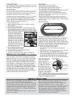
1.
Press the tab in the end of the battery
compartment door to open. (A)
2.
Plug a fully charged 7.2-volt battery
pack into the connector inside. (B)
3.
Twist the battery 2 or 3 times to twirl
the battery plug wires. This helps
hold the wire and battery in place
when the battery is installed in the
compartment. (C)
4.
Install the battery into the
compartment and press the wires
securely into place.
5.
Snap the battery compartment door back on and lock the end tab. (D)
USING THE EZ-START
Your EZ-Start controller plugs into a 4-prong receptacle on the battery
cover of your Nitro Stampede. When the red button on the controller
is pressed, the EZ-Start motor begins to spin the engine and power
from the control unit heats the glow plug. Assuming all settings and
preparations are correct, the engine should start almost immediately.
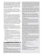
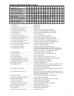
Each of the two status indicator LEDs on
the hand-held control unit, the Motor LED
and the Glow Plug LED, should light green
while starting. If either LED fails to light while
starting, there is a fault indicated with that
function:
If the Glow Plug LED fails to light, the glow
plug may be bad, or the glow plug wire may
be damaged or disconnected.
If the Motor LED fails to light and the starter
fails to operate, then the EZ-Start is in
protection mode.
Protection Mode
The EZ-Start uses Smart Start
®
technology to monitor the
condition of the system and detect failures. The controller
monitors the load being placed on the EZ-Start motor. If the load
becomes excessive, the system shuts off power to the motor to
prevent costly damage to the motor and the controller. This may
occur, for example, if the engine floods with fuel during starting.
The starter spins at first but when excessive fuel in the combustion
chamber begins to lock up the engine, the starter motor slows
under the heavier load. This causes the protection circuit to shut
off the power to the motor. Allow at least three minutes for the
starter motor to cool and the circuit to automatically reset before
continuing. Use the time to find and eliminate the condition that
caused the excessive load on the starter motor.
Use a Strong Starter Battery
A weak starter battery, or one that has not been fully charged,
may not deliver enough power to crank the engine over at the
appropriate rpm to keep the piston from sticking at top dead
center (TDC). A new engine will typically have a tight fit between
the piston and the top of the sleeve. This is a tapered fit, and a tight
piston sleeve fit on initial startup is desirable for those who want
the best-performing engine. Make sure you are using a good quality
battery pack that is fully charged (new batteries usually require
several charge cycles to reach peak voltage and full capacity). This is
especially important with a new engine that needs to be broken in.
STARTING THE ENGINE
Installing the air Filter
Remove the protective cap from the carburetor
air intake. Install the rubber air filter base and pre-
lubed foam element onto the carburetor intake. The
foam air filter element may be cleaned and reused.
always be sure the filter element is oiled properly
before running the engine.
For the best filtration,
use the type of oil made for foam air filters. Traxxas
air filter oil is recommended (part #5263). Lightweight motor oil
or after-run oil may also be substituted. When the element gets
dirty, clean it with dish soap and rinse. Next, saturate it with oil
and then squeeze out the excess oil.
Filling the Fuel Tank
Use a small fuel bottle or bulb to put fuel into the tank. Only fill
the tank to the bottom of the fill neck. The Nitro Stampede can be
carefully refueled while the engine is running.
High-Speed Mixture Setting
The high-speed mixture screw controls how much fuel enters the
engine during mid and high-speed operation. Turn the high-speed
mixture screw clockwise, by hand, until it stops
(Do not tighten
or the needle may be damaged).
Now, turn the mixture screw
counterclockwise 2
1
/
2
complete turns.
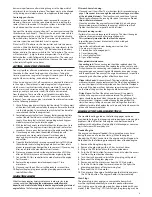
Setting the Idle Speed
The idle screw regulates the throttle
opening to control the idle speed.
The throttle opening at idle should
be set as shown in the drawing.
The opening should be 1 to 1
1
/
2
millimeters at the widest point in
the opening. The engine may not
idle well until it is warmed.
low-Speed Mixture Setting
This screw meters the fuel at low
speeds. The low-speed mixture
screw is located in the end of the
carburetor, inside the throttle arm.
This screw controls how much
fuel enters the engine at idle and
low throttle. This adjustment will
smooth the idle and improve acceleration to mid-speed. Make this
adjustment with the throttle closed, after setting the idle.
Gently
turn
this screw clockwise until it stops against the needle seat. Be very
careful, it’s difficult to know when the needle has seated due to the
thread holding material on the needle’s thread.
Overtightening of the
screw may result in damage to the needle seat.
Now turn the low-
speed mixture screw counterclockwise 1
3
/
4
turns.
NOTE:
Your carburetor has been factory preset for break-in. Do not
re-adjust your carburetor settings unless you suspect a
problem. The following steps are for reference only.
Motor
Glow Plug
Motor
Glow Plug
Motor
Glow Plug
Motor
Glow Plug
Motor
Glow Plug
Motor
Glow Plug
Motor
Glow Plug
Motor
Glow Plug
Motor
Glow Plug
Motor
Glow Plug
Motor
Glow Plug
Motor
Glow Plug
Motor
Glow Plug
Motor
Glow Plug
Motor
Glow Plug
Motor
Glow Plug
Motor
Glow Plug
Motor
Glow Plug
Motor
Glow Plug
Motor
Glow Plug
Motor
Glow Plug
Motor
Glow Plug
Motor
Glow Plug
Motor
Glow Plug
Motor
Glow Plug
Motor
Glow Plug
Motor
Glow Plug
Green LED
Green LED
Red LED
Green LED
Green LED
Red LED
Green LED
Green LED
Red LED
a
B
C
D
2
3
1

