background image

40 

 Revo 3.3

This advanced tuning guide will take you one step further into the 
cutting edge technology that has been designed into Revo. Follow 
the instructions provided here to take advantage of Revo’s maximum 
performance potential. 

SUSPENSION AND ALIGNMENT SETTINGS

Caster Adjustment

The caster angle of the front 
suspension may be used to adjust 
the understeer (push)/oversteer 
handling characteristics of the 
model. Generally, increasing the 
caster angle will move the truck 
towards an oversteer condition 
(more traction on the front tires, less 
on the rear tires). Decreasing the 
caster angle will create a tendency 
towards understeer (pushing in the 
turns). From the factory, the front 
suspension is set to a caster angle of 
10-degrees. The rear caster angle is 
not adjustable. The caster angle 
of the front suspension can be 
adjusted from 5° to 15°. Adjust 
the caster by positioning the 
caster adjustment shims on the 
upper control arms of the front 
suspension as shown in the 
table to the right.

Caster Angle, and Bump Steer

Bump steer is unwanted change in the steering angle of the front wheels  
as the suspension travels up and down. It can result in unstable and 
unpredictable handling. Bump steer is affected by the position of the 
outer toe link end on the axle carrier. From the factory, the toe links are 
positioned so that bump steer is virtually eliminated (about 3/100 of 
a degree through the entire range of travel). When the caster angle is 
changed, the outer toe link end should be repositioned on the axle carrier 
to maintain zero bump steer geometry. Adjustment is achieved using the 
shims and hollow balls provided with the vehicle. Refer to the Bump Steer 
Elimination chart on page 41,  and look up your caster angle setting to 
find the correct position for the outer toe links. Positioning the toe-links 
correctly will maintain the original factory geometry and eliminate the 
unwanted steering angle changes caused by bump steer.

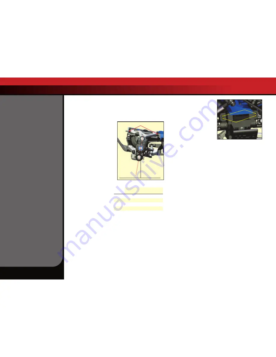
Roll Center

There are two holes on the 
bulkheads to mount each upper 
suspension arm. The roll center 
of the vehicle can be raised by 
mounting the upper control arm in 
the lower of the two holes. This will 
effectively increase the roll stiffness 
of the vehicle (similar to installing 
swaybars). Adding roll resistance to 
one end of the vehicle will tend to 
add traction to the opposite end. For example, increasing roll resistance in 
the rear by installing the upper arms in the lower holes will provide more 
traction for the front wheels and potentially more steering. Installing the 
upper arms in the lower holes on the front and rear will increase overall roll 
resistance without changing the handling balance. The arms are installed 
in the upper position in the front and lower position in the rear from the 
factory to make the truck easier and more forgiving to drive and less likely 
to traction roll in turns. Changing the arm positions should be reserved 
for track tuning. 

Note

: when the upper suspension arms are moved to 

a different hole, the front outer toe link ends and rear toe control links 
should be repositioned to eliminate bump steer. Refer to the  Bump Steer 
Elimination chart on page 41, and look up your suspension combination 
(caster angle and roll center position) to find the correct position for the 
front outer toe links and the rear toe control links. Adjustment is achieved 
using the shims and hollow balls provided with the vehicle.

Rockers (Progressive Rate/ Suspension Travel)

One of the most exciting aspects of Revo’s suspension is the inboard 
shock (damper) arrangement that uses pivoting rockers to translate 
vertical wheel travel into linear shock motion. The rockers can be changed 
to increase or decrease the maximum wheel travel and also to change the 
progressive rate of the suspension. 
The progressive rate determines how much the force at the wheel 
produced by the springs being compressed (wheel force) will vary with 
suspension travel (or vertical travel of the wheel). On a progressive 
suspension arrangement, the wheel force will increase at a faster and 
faster rate as the suspension is compressed. It feels as though the shock 
spring gets progressively stiffer the more you compress the suspension. 
On a linear suspension arrangement, the wheel force increases linearly as 
the suspension is compressed. The spring does not feel any stiffer, even 
when the suspension is fully compressed. This provides a very “plush” 
feeling suspension with seemingly bottomless suspension travel.

Caster adjustment shims (2 front, 2 rear)

Vertical

Ground plane

10°

Upper Control Arm

Upper Mounting Holes

Upper Control Arm

Lower Mounting Holes

Caster

In Front of 

Hinge Pin Boss

Behind Hinge 

Pin Boss

5.0°

None

Four

7.5°

One

Three

10.0°

Two

Two

12.5°

Three

One

15.0°

Four

None

Number & Position of Caster Adjustment 

Shims (Front Upper Control Arm)

ADVANCED TUNING ADjUSTMENTS

Summary of Contents for Revo 3.3 5309

Page 1: ...MODEL 5309 owners manual...

Page 2: ...axxas engineers designed into Revo Even if you are an experienced R C enthusiast it s important to read and follow the procedures in this manual Revo contains new technologies in the engine suspension...

Page 3: ...Traxxas com You may also e mail customer support with your question at support Traxxas com Join thousands of registered members in our online community at Traxxas com Traxxas offers a full service on...

Page 4: ...n the presence of fuel or fuel vapors The engine brakes and exhaust system may become extremely hot during use Be careful not to touch the parts especially when refueling or stopping the engine Prolon...

Page 5: ...see Use the Right Batteries on page 10 Glow plug wrench Extra glow plug 17mm wheel wrench 1 5mm L wrench 2 0mm T wrench 2 5mm T wrench 8mm slipper clutch wrench Shock wrench 5mm turnbuckle wrench Susp...

Page 6: ...ressure Line Fuel Line EZ Start Motor EZ Start Plug Bulkhead under chassis Body Mount Post Chassis Slipper Clutch under roll hoop Spur Gear under roll hoop Driveshaft Half Shaft On Off Switch Shift Ro...

Page 7: ...r the transmitter sold separately Follow the break in instructions exactly to ensure the best performing longest lasting engine 5 Install the EZ Start battery See page 24 13 Tune your engine See page...

Page 8: ...en trying to smooth it out will result in air pockets Antenna On Off Switch Receiver RX Power Pack 5 cell NiMH Battery Steering Servos Throttle Servo Shifting Servo micro servo OptiDrive ESM Electroni...

Page 9: ...on the 2 4GHz digital spread spectrum system mAh Abbreviation for milliamp hour A measure of the capacity of the battery pack The higher the number the longer the battery will last between recharges N...

Page 10: ...attery on the floor or in other locations where someone may accidentally damage or disconnect the battery When plugged in the charger s LED will glow green indicating the charger is ready to begin cha...

Page 11: ...tage After connecting a fully drained battery to the charger it may take up to 15 seconds for the charger to sense the battery and begin to charge To start charging immediately plug the battery pack i...

Page 12: ...o adjust the OptiDrive and readjust the throttle and brake linkages to operate properly with the new throttle neutral setting Electronic Throttle Trim The electronic throttle trim located on the face...

Page 13: ...een twice and then release the button immediately You are now in programming mode 4 Pull the transmitter throttle trigger to the full throttle position Hold it there until the Function LED flashes gre...

Page 14: ...eck that the steering mechanism is not loose or binding If the steering operates slowly then check the receiver pack to make sure it is fully charged 5 When looking down at model the front wheels shou...

Page 15: ...ail safe mode has been deactivated Use these steps to reactivate the fail safe system 1 Switch the transmitter and receiver on 2 Press and hold the receiver s LINK button The LED will flash once then...

Page 16: ...premature engine wear and failure is lack of care and maintenance BREAK IN The TRX 3 3 Racing Engine is manufactured to exacting tolerances and requires a specially designed break in procedure to acco...

Page 17: ...l Carburetor Air Intake Fuel Intake High Speed Needle Idle Speed Screw Clutch Bell Crankcase Two Stage Air Filter Glow Plug EZ Start Plug Positive Wire Negative Wire Fuel Line Fuel Tank Tuned Pipe Hea...

Page 18: ...ngine s body that contains all of the running mechanical components Crankshaft The main shaft of the engine that holds the reciprocating assembly Cooling fins The cooling fins are milled into the cyli...

Page 19: ...the first level of air filtration for the engine The majority of dirt and debris will be stopped by this filter Clean re oil and replace this filter after every hour of run time Always use both the p...

Page 20: ...limitations Engines are designed to run best within a range of nitro percentages How the engine is ported the size of the combustion chamber and other factors determine how much nitro can be efficien...

Page 21: ...t pull straight up 2 Remove the pre filter element 3 Clean the pre filter element by thoroughly washing the foam element in hot soapy water dishwashing detergent works well Repeat twice 4 Thoroughly d...

Page 22: ...rect air fuel ratio The tuning needles are there to adjust how much fuel is made available for the carburetor to mix with the available air atomization The Fuel Mixture Needles The amount of fuel mete...

Page 23: ...unning to assess what minor adjustments may be required to compensate for fuel temperature and altitude Adjustments are usually made in 1 8 or 1 16 turn increments If the engine sticks at top dead cen...

Page 24: ...tery in place when the battery is installed in the compartment C 4 Install the battery into the compartment and press the wires securely into place 5 Snap the battery compartment door back on and lock...

Page 25: ...piston and the top of the sleeve This is a tapered fit and a tight piston sleeve fit on initial startup is desirable for those who want the best performing engine Make sure you are using a good quali...

Page 26: ...e Change or clean your air filter after break in Follow the instructions exactly for each of the first 5 tanks of fuel Starting Your TRX 3 3 Racing Engine for the First Time Before you start your TRX...

Page 27: ...3 When the fuel tank is nearly empty shut off the engine and refuel From here on you do not need to let the engine cool between tanks Tank 4 1 Driving procedure Gently pull the throttle trigger to fu...

Page 28: ...is over 220 F and needs to cool down If the water takes a long time or does not evaporate at all then the engine is too cool We do not recommend that you operate your engine below 35 Fahrenheit If yo...

Page 29: ...unterclockwise and retest This setting will extend engine component life Low Speed Fuel Mixture Adjustment The low speed mixture is always set after the high speed needle is correctly adjusted The low...

Page 30: ...uence on engine temperature is air temperature Expect the engine temperature to vary almost in direct proportion to air temperature Assuming you tuned the engine for the same maximum performance each...

Page 31: ...ted by speed Towing creates a high load on the engine and at the same time limits cooling of the engine due to low vehicle speed If your Revo gets stuck stop driving immediately Move the vehicle and t...

Page 32: ...d rear springs on Revo have different spring rates The rear springs are about 10 stiffer than the front springs The spring s pre load tension can be adjusted by turning the spring pre load adjuster Ad...

Page 33: ...ion damping to be reduced Damping should be increased with higher viscosity oil if the model is bottoming easily over jumps Damping should be decreased with thinner viscosity oil if the model is hoppi...

Page 34: ...he wheel moves up and down through its range of travel Static camber is the camber angle at the wheel when the vehicle is set at its normal stationary ride height The suspension pivot balls located in...

Page 35: ...ole in the end of the slipper shaft This locks the shaft for adjustments Turn the adjustment nut clockwise to tighten less slippage and counter clockwise to loosen more slippage The slipper clutch has...

Page 36: ...djusting the Spur Gear Clutch Bell Gear Mesh The ideal spur gear clutch bell gear mesh for Revo is 0 1mm To set the gear mesh place a strip of standard letter A4 size copy or printer paper about 0 1mm...

Page 37: ...in one of the following ways 1 Use a 0 50mm feeler gauge between the brake pad insert and brake disk 2 Push the outer brake pad firmly against the inner pad with your finger sandwiching the brake dis...

Page 38: ...uld be replaced when they no longer seal effectively loss of compression Symptoms include the engine being difficult to start when warm stalling when warm and stalling when throttle is suddenly closed...

Page 39: ...blue glow plug wire to the glow plug 7 Reconnect the EZ Start controller 8 Do not prime the engine Pull the throttle to 1 2 throttle and push the EZ Start button The engine should start immediately P...

Page 40: ...to the opposite end For example increasing roll resistance in the rear by installing the upper arms in the lower holes will provide more traction for the front wheels and potentially more steering Ins...

Page 41: ...of the various rocker arms on wheel force as the suspension is compressed On the progressive rate wheel force is light at first and increases as the suspension is compressed Bump Steer Elimination Cha...

Page 42: ...ly move the piston up and down always keeping it submerged in oil to release the air bubbles Let the shock sit for a few minutes to allow any remaining air bubbles to surface 10 Slowly thread the uppe...

Page 43: ...ts and to the rocker arms 2 Install long travel shock springs Replace all four of the 90mm travel shock springs with the four 120mm long travel shock springs The front shock springs are indicated by a...

Page 44: ...1100 Klein Road Plano Texas 75074 1 888 TRAXXAS 090625 KC1185 R01 MODEL 5309 owners manual...

Reviews: