background image

REVO PLATINUM EDITION • 11 

TUNING ADJUSTMENTS

Roll Center

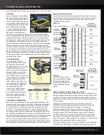
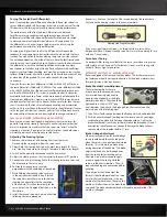
There are two holes on the bulkheads 
to mount each upper suspension arm. 
The roll center of the vehicle can be 
raised by mounting the upper control 
arm in the lower of the two holes. This 
will effectively increase the roll stiffness 
of the vehicle (similar to installing 
swaybars). Adding roll resistance to 
one end of the vehicle will tend to 
add traction to the opposite end. 
For example, increasing roll resistance in the rear by installing the upper 
arms in the lower holes will provide more traction for the front wheels and 
potentially more steering. Installing the upper arms in the lower holes on 
the front and rear will increase overall roll resistance without changing the 
handling balance. From the factory, the arms are installed in the upper 
position in the front and the lower position in the rear for track tuning. 

Note:


When the suspension arms are moved to the either mounting holes, the 
front outer toe link ends and the rear toe control links should be repositioned 
to eliminate bump steer. Refer to the Bump Steer Elimination chart on this 
page, and look up your suspension combination (caster angle and roll center 
position) to find the correct position for the front outer toe links and the rear 
toe control links. Adjustment is achieved using the shims and hollow balls 
provided with the vehicle.

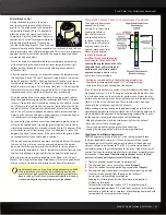
Caster Adjustment

The caster angle of the front 
suspension may be used to adjust 
the understeer (push)/oversteer 
handling characteristics of the model. 
Generally, increasing the caster 
angle will move the truck towards an 
oversteer condition (more traction 
on the front tires, less on the rear 
tires). Decreasing the caster angle will 
create a tendency towards understeer 
(pushing in the turns). From the 
factory, the front suspension is set 
to a caster angle of 15-degrees. The 
rear caster angle is not adjustable. 
The caster angle of the front 
suspension can be adjusted from 
5° to 15°. Adjust the caster by 
positioning the caster adjustment 
shims on the upper control arms 
of the front suspension as shown 
in the table to the right.

Caster Angle, and Bump Steer

Bump steer is unwanted change in the steering angle of the wheels as the 
suspension travels up and down. It can result in unstable and unpredictable 
handling. Bump steer is affected by the position of the outer toe link end 
on the axle carrier. From the factory, the toe links are positioned so that 
bump steer is virtually eliminated (about 3/100 of a degree through the 
entire range of travel). When the caster angle is changed, the outer toe link 
end should be repositioned on the axle carrier to maintain zero bump steer 
geometry. Adjustment is achieved using the shims and hollow balls provided 
with the vehicle. Refer to the Bump Steer Elimination chart and look up 
your caster angle setting to find the correct position for the outer toe links. 
Positioning the toe-links correctly will maintain the original factory geometry 
and eliminate the unwanted steering angle changes caused by bump steer.

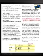
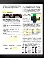
Bump Steer Elimination Chart

The illustrations and the following table detail the position of the outer 
toe link end for various caster and roll center settings to eliminate bump 
steer. The shims and the hollow balls used to adjust bump steer are 
provided with your vehicle.

REAR

When the rear upper control 
arms are mounted in the upper 
of its two mounting holes in 
the bulkhead (roll center), the 
tall lower hollow ball should 
be used.

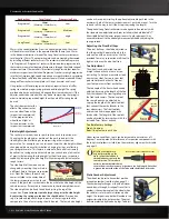
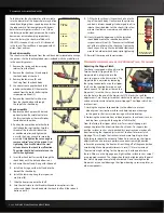
Rockers (Progressive Rate/ Suspension Travel)

One of the most exciting aspects of Revo’s suspension is the inboard shock 
(damper) arrangement that uses pivoting rockers to translate vertical wheel 
travel into linear shock motion. The rockers can be changed to increase or 
decrease the maximum wheel travel and also to change the progressive rate 
of the suspension. 
The progressive rate determines how much the force at the wheel 
produced by the springs being compressed (wheel force) will vary with 
suspension travel (or vertical travel of the wheel). On a progressive 
suspension arrangement, the wheel force will increase at a faster and 
faster rate as the suspension is compressed. It feels as though the shock 
spring gets progressively stiffer the more you compress the suspension. 
On a linear suspension arrangement, the wheel force increases linearly as 
the suspension is compressed. The spring does not feel any stiffer, even 
when the suspension is fully compressed. This provides a very “plush” feeling 
suspension with seemingly bottomless suspension travel.
A total of four different rocker arm sets are available for Revo. All rocker arms 
except the Long Travel rocker arms will allow the wheel to travel a total of 

SUSPENSION AND ALIGNMENT SETTINGS

Caster adjustment shims (4 front, 0 rear)

Vertical

Ground plane

15°

Caster

In Front of 

Hinge Pin Boss

Behind Hinge 

Pin Boss

5.0°

None

Four

7.5°

One

Three

10.0°

Two

Two

12.5°

Three

One

15.0°

Four

None

Number & Position of Caster Adjustment 

Shims (Front Upper Control Arm)

Upper Control Arm

Upper Mounting Holes

Upper Control Arm

Upper Mounting Holes

Upper Control Arm

Lower Mounting Holes

Upper Control Arm

Lower Mounting Holes

Outer Toe Link End Setup

Caster

    5°    7.5°    10°    12.5°    15°

Control Arm 

Mounting Hole on 

Front Bulkhead

Upper

Lower

Upper

Lower

Upper

Lower

Upper

Lower

Upper

Standard 

Hollow Ball
Thin Shim
Thick Shim

Thin Shim
Standard

Hollow Ball
Thick Shim

Tall Center 

Hollow Ball

Thick Shim
Standard

Hollow Ball
Thin Shim

Thick Shim
Thin Shim
Standard

Hollow Ball

FRONT

Control Arm 

Mounting Hole on 

Rear Bulkhead

Outer Toe Link 

End Setup

Upper

Lower

Tall Center 

Hollow Ball 

(stock)

Tall Lower 

Hollow Ball

5304 Manual Work.indd   11

3/12/08   7:47:37 PM

Summary of Contents for Revo 5304 Platinum Edition 2008

Page 1: ...2 0 0 8 P l a t i n u m E d i t i o n MODEL 5304 ...

Page 2: ...st with your truck but also with the company that stands behind it We truly want you to enjoy your new Revo Thank you again for going with Traxxas BEFORE YOU PROCEED Carefullyreadandfollowallinstructionsinthisandanyaccompanying materials to prevent serious damage to your Revo Failure to follow these instructions will be considered abuse and or neglect Before running your Revo look over this entire...

Page 3: ... directions around your model to prevent collisions The engine can be loud If the noise makes you uncomfortable wear ear protection Be considerate of your neighbors by not running your model early in the morning or late in the evening Most importantly use good common sense at all times Children under 16 years of age and inexperienced drivers should not operate the Revo without the supervision of a...

Page 4: ...e truck Revo has a charging jack located inside the receiver box so you do not have to remove the battery pack from the model To charge the battery remove the receiver box cover and plug the charger output cord into the charging jack The on off switch must be in the off position to charge the receiver pack Caution Never charge batteries in an enclosed car interior or while driving Never leave char...

Page 5: ...sk the windows Mask off any stripes or custom effects with either masking tape or special tape made for striping This special tape is available from automotive paint supply stores and will provide sharper edges than masking tape For easy custom colored striping automotive pin striping tape can be applied to the inside of the body and painted over Be sure that all of your tape and masks are fully p...

Page 6: ...details about your new engine THE FUEL Use the Right Fuel It s imperative that you use the correct fuel in your TRX 3 3 Racing Engine for maximum performance and engine life Traxxas Top Fuel should be used to ensure correct engine lubrication performance and ease of tuning Traxxas Top Fuel has been proven in thousands of engines so you can count on it every day for great performance Top Fuel is th...

Page 7: ... and replace the glow plug with a new one after the engine break in procedure Engine Break in Procedure The focus during break in is to vary and limit the engine speed This will be accomplished by accelerating and stopping at different rates for the first 5 tanks of fuel As the engine begins to break in the duration and intensity of the acceleration will gradually increase Sustained high speed run...

Page 8: ...to stop Count the two seconds out while accelerating one thousand one one thousand two and then stop Repeat this starting and stopping procedure until the second tank of fuel is nearly empty 3 When the fuel tank is nearly empty shut off the engine and let it cool for 15 minutes Tank 3 1 Driving procedure Gently pull the throttle trigger to 1 2 throttle over a 3 second count Then gently apply the b...

Page 9: ...NG ENGINE The engine s performance depends on the fuel mixture Turn the mixture needles clockwise to lean the fuel mixture and counterclockwise to richen it Leaning the fuel mixture will increase engine power up to the engine s mechanical limits Never run the engine too lean not enough fuel flow Never lean the engine until it begins to cut out or stall Leaning the engine beyond the safe allowable ...

Page 10: ...ning aid when you understand the relationship between engine temperature and ambient temperature The engine operating temperature when tuned for maximum performance will vary according to atmospheric conditions engine load gauge accuracy and many other factors The atmospheric condition that has the most influence on engine temperature is air temperature Expect the engine temperature to vary almost...

Page 11: ...ow balls provided with the vehicle Refer to the Bump Steer Elimination chart and look up your caster angle setting to find the correct position for the outer toe links Positioning the toe links correctly will maintain the original factory geometry and eliminate the unwanted steering angle changes caused by bump steer Bump Steer Elimination Chart The illustrations and the following table detail the...

Page 12: ...er spring should be used The lowest ride height can be achieved by installing the optional adjustable push rod in the outermost hole of the lower suspension arm s push rod mount Turn the rod ends all the way in until they stop shortening the length The optional Long Travel rocker arms are designed to be used only with the standard non adjustable push rods installed in the hole labeled LT the middl...

Page 13: ...sag reduce body lean control brake dive and provide a firmer more responsive overall feel If Revo is lightened significantly softer springs will be necessary to allow the suspension to sag properly Heavier configurations will require stiffer springs Ride height is adjusted by changing the length or position of the push rods in the lower suspension arms See Ride Height Adjustments on page 12 The su...

Page 14: ...aining air bubbles to surface 10 Slowly thread the upper cap with the installed shock bladder onto the shock body with the suspension multi tool A The excess oil will bleed out of the small hole in the shock cap Tighten the shock cap until snug Use the included steel shock wrench to hold onto shock body while tightening 11 Reinstall the spring and lower retainer TRANSMISSION AND DIFFERENTIAL TUNIN...

Page 15: ... inset 3 Carefully remove the engine and exhaust system from the spur gear area to allow enough room to remove the spur gear 4 Remove the three screws on the slipper clutch assembly using a 2 5mm hex wrench Slide the spur gear off of the slipper shaft If the spur gear is too tight on the shaft gently pry on the back of the gear with a flat screw driver to loosen it Repeat the above steps in revers...

Page 16: ... Template below to set length 3 Switch on the power to the receiver and the transmitter 4 Adjust the steering trim on the transmitter to the neutral 0 position 5 Connect one end of a steering link to the steering servo saver arm and the other end to the servo horn 6 Position the steering servo saver arm perpendicular to the centerline of the vehicle 7 While holding the steering servo saver arm in ...

Page 17: ... in both unloaded and loaded suspension conditions Always adjust the left and right sway bar links equally to prevent suspension tweak The Adjustable hollow balls can be raised or lowered closer to or further from the sway bar mount pivot point to increase torsion response and fine tune the sway bar s response for different track conditions Closer to the pivot point results in a stiffer setup furt...

Page 18: ...e Speed Adjustment 10 Low Speed Fuel Mixture Adjustment 10 Painting 5 Receiver 3 4 antenna 4 battery See RX Power Pack RX Power Pack 4 care 4 Safety 3 Servos steering 4 16 throttle 4 Shocks 13 assembly 14 disassembly 14 pistons 13 Slipper clutch 14 Springs 13 Spur gear changing 15 mesh 15 Starter box 3 6 8 Steering 16 Supplies 3 Support 2 Suspension and Alignment 11 12 bump steer 11 elimination 11...

Page 19: ...REVO PLATINUM EDITION 19 NOTES ...

Page 20: ...080312 KC1126 1100 Klein Road Plano Texas 75074 1 888 TRAXXAS ...

Reviews: