background image

SLASH 4X4 ULTIMATE • 7

QUICK START: GETTING UP TO SPEED

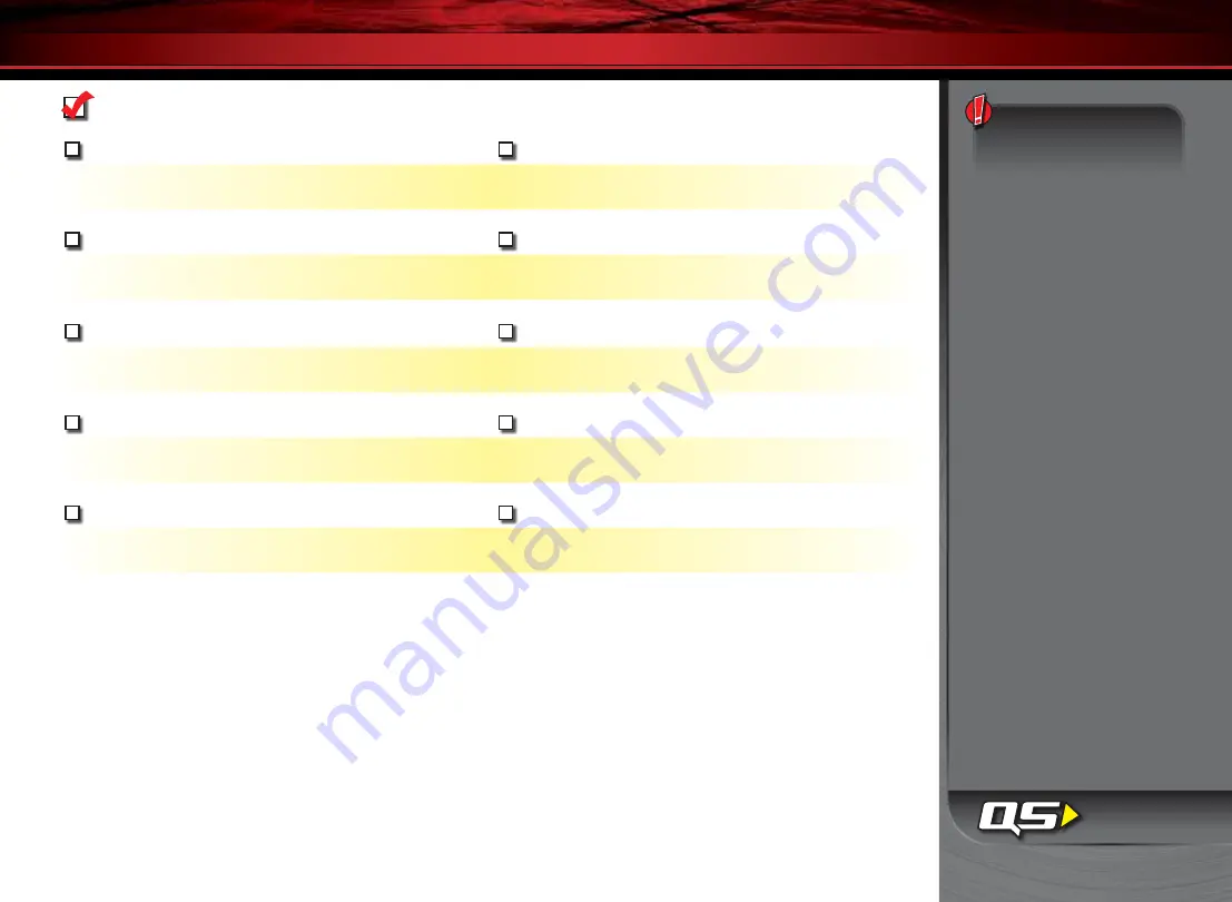
The following guide is an overview of the procedures for getting your model running. Look for the Quick Start logo on the bottom 
corners of Quick Start pages.

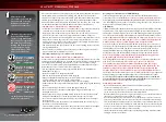
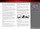
     1.   Read the safety precautions on page 4

     6.   Check servo operation • See page 14

For your own safety, understand where carelessness and misuse 
could lead to personal injury and product damage.

Make sure the steering servo is working correctly.

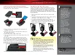
     2.   Charge the battery pack • See page 11

     7.   Range test the radio system • See page 14

Fully charge the included battery pack. Begin charging  
your battery right away.

Follow this procedure to make sure your radio system works properly at 
a distance and that there is no interference from outside sources.

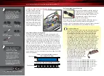
     3.   Install batteries in the transmitter • See page 11

     8.   Detail your model • See sidebar, page 8

The transmitter requires 4 AA alkaline or rechargeable batteries.

Apply other decals if desired.

     4.   Install the battery pack in the model • See page 12

     9.  Drive your model • See page 18

Your model requires a fully charged battery pack.

Driving tips and adjustments for your model.

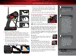
     5.   Turn on the radio system • See page 13

     10.  Maintaining your model • See page 22

Make a habit of turning the transmitter on first, and off last.

Follow these critical steps to maintain the performance 
of your model and keep it in excellent running condition.

The Quick Start Guide is 
not intended to replace the 
full operating instructions 
available in this manual. 
Please read this entire 
manual for complete 
instructions on the proper 
use and maintenance of 
your model.

Look for the Quick Start 
logo at the bottom of 
Quick Start pages.

Summary of Contents for Slash 4x4 Ultimate 6807

Page 1: ...owner s manual MODEL 6807...

Page 2: ...h Traxxas Link and precise control over a wide array of tuning adjustments The high capacity 4200mAh Series 4 battery pack is 7 cells of pure speed at 40 mph Officially licensed racing graphics comple...

Page 3: ...mage to your model Failure to follow these instructions will be considered abuse and or neglect Before running your model look over this entire manual and examine the model carefully If for some reaso...

Page 4: ...ry Traxxas strongly encourages you to recycle your Power Cell battery when it has reached the end of its useful life Do not throw your battery in the trash All Power Cell battery packs display the RBR...

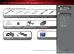
Page 5: ...nd or needle nose pliers Philips screwdriver Soldering iron For more information on batteries see Use the Right Batteries on page 11 U joint wrench supplied tools and equipment 4 AA alkaline batteries...

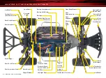
Page 6: ...Hold Down Battery Receiver Box Antenna Mount Front Suspension Arm Front Bumper Steering Servo Shock Oil Damper Turnbuckle Toe Link Turnbuckle Front Camber Link Turnbuckle Rear Camber Link Rear Shock...

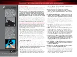
Page 7: ...ence from outside sources 3 Install batteries in the transmitter See page 11 8 Detail your model See sidebar page 8 The transmitter requires 4 AA alkaline or rechargeable batteries Apply other decals...

Page 8: ...ectronics that energize the electromagnetic windings in sequence to provide rotation Opposite of a brushed motor the brushless motor has its windings coils on the perimeter of the motor can and the ma...

Page 9: ...ctions to your model Trim The fine tuning adjustment of the neutral position of the servos made by adjusting the throttle and steering trim knobs on the face of the transmitter Note The Multi Function...

Page 10: ...c Speed Control Channel 1 Steering Servo to Motor LED EZ Set Button On Off Button Heat Sink VXL 3s ELECTRONIC SPEED CONTROL Traxxas High Current Connector Male to Battery Motor Cap Traxxas High Curren...

Page 11: ...with the included charger The LED will turn green when the battery is fully charged Disconnect the battery from the charger after charging Using Other Chargers Another convenient option for charging...

Page 12: ...nt flow and are not capable of delivering the power needed to maximize the output of the Velineon Brushless Power system The Traxxas connector s gold plated terminals with a large contact surfaces ens...

Page 13: ...cating a failure to link If you miss it simply turn off the transmitter and start over Always turn on the transmitter before plugging in the battery TQ 2 4GHz Radio System Basic Adjustments Throttle N...

Page 14: ...arning Do not apply full throttle in forward or reverse while the model is elevated 8 Once adjustments are made turn off the receiver on your model followed by the hand held transmitter Range Testing...

Page 15: ...eased Steering Sensitivity Negative Exponential By turning the Multi Function knob clockwise the steering sensitivity of the model will be decreased Note that a relatively large amount of steering whe...

Page 16: ...our transmitter is properly adjusted set back to the factory defaults Otherwise you may not get the best performance from your speed control The transmitter should be adjusted as follows If the transm...

Page 17: ...reen Low Voltage Detection ACTIVE or red Low Voltage Detection DISABLED The model is ready to drive SelectingTrainingMode Profile 3 50 Forward 100 Brakes 50 Reverse 1 Connect a fully charged battery p...

Page 18: ...arger Read and follow all maintenance and care instructions provided by the manufacturer of your batteries and charger Keep the VXL 3s cool Get plenty of airflow across the ESC heat sinks Use the corr...

Page 19: ...iver It is not necessary to remove the receiver or unplug any of the wires 9 Additional Maintenance Increase your frequency of disassembly inspection and lubrication of the following items This is nec...

Page 20: ...sure the same amount of steering in both directions Front Toe In For increased stability add one to two degrees of toe in to each front wheel Use the turnbuckles to adjust the alignment Rear Toe In Yo...

Page 21: ...r s batteries are no depleted 4 Turn the transmitter s steering trim knob to the center 0 position 5 Disconnect motor wires A and C see page 10 to prevent the motor from turning during the next steps...

Page 22: ...ension pins bent turnbuckles loose screws and any signs of stress or bending Replace components as needed Steering Over time you may notice increased looseness in the steering system The tie rod ends...

Page 23: ...r the chassis 4 Pull the front suspension assembly away from the chassis Removing the rear suspension module Slipper clutch assembly removal 1 Remove the two 4x12 button head cap screws from the top o...

Page 24: ...r correction Bump steer refers to unwanted steering inputs caused by suspension movement Slash 4X4 s suspension geometry is designed to minimize bump steer If you are using the upper hole on the C hub...

Page 25: ...rection of rotation Refer to the wiring diagram on page 10 Sensored Brushless Motors The VXL 3s is fully compatible with sensored brushless motors Sensor motors use an additional sensor installed in t...

Page 26: ...the oil in the differential with either lower or higher viscosity oil will vary the performance characteristics of the differentials Changing to a higher viscosity oil in the differential will reduce...

Page 27: ...ure the rubber gasket is in place or the differential may leak 5 Install the 2 5x10mm screws and tighten securely Center differential The optional included center differential allows the power from th...

Page 28: ...thicker oils provide more damping Use only 100 pure silicone shock oil to prolong seal life Lower viscosity fluid lower oil weight less damping force More or larger piston holes less damping force In...

Page 29: ...wer retainer SWAY BAR SETTINGS AND ADJUSTMENTS Adjust the sway bar links so the sway bars are level parallel to the ground when the truck is on the ground and the suspension is at rest normal ride hei...

Page 30: ...end point adjustment settings you select will represent what you wish to be the servo s maximum travel the Steering Percentage or Braking Percentage functions will not override the End Point settings...

Page 31: ...times repeatedly 4 Press SET once The status LED will blink green once repeatedly 5 Press MENU once The status LED will blink green twice repeatedly 6 Press SET The memory is now selected to be delet...

Page 32: ...set to save Push forward to desired endpoint and press set to save To reset max throw Let go of controls and press SET The menu tree below shows how to navigate through the TQ 2 4GHz transmitter s var...

Page 33: ...reen LED blinks Press SET red LED blinks x3 Press MENU twice red LED blinks x3 Turn steering wheel to desired max left and right travel x8 Press SET to save each position Turn steering wheel to test s...

Page 34: ...il __________ wt Oil __________ wt Piston 1 hole Piston 1 hole Piston 2 hole Piston 2 hole Piston 3 hole Piston 3 hole Battery Placement Front Tire Type_________________ Tire Insert_ _______________ W...

Page 35: ...___ Weight _______lbs Springs Color ___________________ Preload _________mm ______mm ______mm Springs Color ___________________ Preload _________mm Oil __________ wt Oil __________ wt Piston 1 hole Pi...

Page 36: ...1100 Klein Road Plano Texas 75074 1 888 TRAXXAS 110411 KC1299 R01 owner s manual...

Reviews: