10
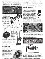
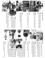
STEP 7:
T
o separ
ate the engine from the engine mount,
remo
v
e the f
our 3x8mm caphead machine scre
ws
.
* Note:
Y
ou will not need to remo
v
e the engine mount
for a basic reb
uild of the engine
.
Do remo
v
e the engine
mount if y
ou e
xchanging the engine under the Lif
etime
Engine Replacement Plan.
REB
UILDING
THE ENGINE
STEP 1:
Unplug the b
lue wire from the glo
w plug.
Remo
v
e the
fuel line from the carb
uretor pressure fitting.
Disconnect the red and b
lac
k wires from the EZ-Star
t
motor
.
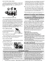
STEP 8:
Remo
ving the carb
uretor is not necessar
y to reb
uild
the engine
, unless y
ou intend to replace the inter
nal
bear
ings of the engine
.
Remo
v
e the carb
uretor b
y
loosening the 3mm loc
kn
ut and pulling the carb
uretor
str
aight up
.
Do not lose the r
ub
ber O-r
ing.
STEP 9:
Use the tip of a small scre
wdr
iv
er to remo
v
e the E-clip
which holds the clutch bell gear
.
STEP 10:
Remo
v
e the clutch bell gear and the clutch shoes
.
Note that there are tw
o 5x8mm
T
eflon
®
w
ashers
, one
on each side of the clutch bell gear
.
Chec
k the clutch
shoes f
or e
xcessiv
e w
ear or
cr
ac
king around the pin
holes
.
If the clutch shoes
are w
or
n to the point that
the clutch spr
ing contacts
the clutch bell, then the
shoes m
ust be replaced.
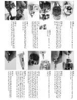
STEP 11:
Gr
ip the flywheel with a pair
of pliers (loc
king pliers w
or
k
best).
Remo
v
e the clutch
adapter n
ut with a 10mm
deep soc
k
et.
Hold the
engine just abo
v
e y
our
w
or
kbench and tap the fly
-
wheel from behind with a
non-marr
ing hammer (plas
-
tic or w
ood).
Se
v
er
al easy b
lo
ws ma
y be necessar
y to
release the flywheel and split be
v
eled cone
.
STEP 12:
The flywheel and the split-be
v
eled
cone should pull
smoothly
off of the cr
ankshaft.
STEP 2:
Remo
v
e the e
xhaust hangar bolt which secures the
tuned pipe to the chassis
.
Pull the tuned pipe from the
header
.
STEP 3:
Use a 2.5mm he
x dr
iv
er to remo
v
e the f
our engine
mount scre
ws from the bottom of the chassis
.
STEP 4:
Pull the engine out of the tr
uc
k.
Remo
v
e the y
ello
w
g
round wire from the engine mount.
No
w y
ou can
completely remo
v
e the engine
.
STEP 5:
Pull the engine from the chassis
.
T
ur
n
the engine so that the throttle linkage
to the carb
uretor will come out.
Remo
v
e the EZ-Star
t gearbo
x b
y
remo
ving the three 3x8mm roundhead
machine scre
ws
.
STEP 6:
Remo
v
e the 3x23mm roundhead machine scre
ws that
fasten the header to the engine
.
Carefully remo
v
e the
header to a
v
oid damaging the gask
et.

