background image

18 • X-MAXX

ADJUSTING THE ELECTRONIC SPEED CONTROL

Patented Training Mode 
(Profile #3) reduces forward 
and reverse throttle by 50%. 
Training Mode is provided 
to reduce the power output, 
allowing beginning drivers 
to better control the model. 
As driving skills improve, 
simply change to Sport or 
Race Mode for full-power 
operation.

The VXL-6s has built-in 
programming that prevents 
accidental activation of 
reverse while in forward 
motion and vice-versa. You 
must come to a complete 
stop, release the throttle 
trigger, then apply opposite 
throttle to engage the motor 
in the desired direction.

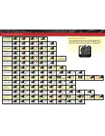
Selecting Race Mode


(Profile #2: 100% Forward, 100% Brakes, No Reverse)
1. Connect a fully charged battery pack to  

the VXL-6s and turn on your transmitter.

2. With the VXL-6s off, press and hold  

the EZ-Set button until the LED turns 
solid green, then solid red and then 
begins blinking red (indicating the Profile 
numbers).

3. When the LED blinks red twice, release  

the EZ-Set button.

4. The LED will blink and then turn solid green (Low-Voltage Detection 

ACTIVE) or red (Low-Voltage Detection DISABLED). The model is 
ready to drive.

Selecting Training Mode


(Profile #3: 50% Forward, 100% Brakes, 50% Reverse)
1. Connect a fully charged battery pack to 

the VXL-6s and turn on your transmitter.

2. With the VXL-6s off, press and hold the EZ-

Set button until the LED turns solid green, 
then solid red and then begins blinking 
red (indicating the Profile numbers).

3. When the LED blinks red three times, 

release the EZ-Set button.

4.


The LED will blink and then turn solid 
green (Low-Voltage Detection ACTIVE) or red (Low-Voltage 
Detection DISABLED). The model is ready to drive.

Note:

 If you missed the mode you wanted, keep the EZ-Set button 

pressed down and the blink cycle will repeat until the button is 
released and a Mode is selected.

LED Codes and Protection Modes

• Solid Green

: VXL-6s power-on light. Low-Voltage Detection is 

ACTIVATED (LiPo setting).

• Solid Red

: VXL-6s power-on light. Low-Voltage Detection is 

DISABLED (NiCad/NiMH setting). 

Never use LiPo batteries 

while Low-Voltage Detection is disabled. 

• Slow Blinking Red 

(with Low-Voltage Detection on):  The 

VXL-6s has entered 

Low-Voltage Protection

.  When the 

battery voltage begins to reach the minimum recommended 

discharge voltage threshold for LiPo battery packs, the VXL-6s 
will limit the power output to 50% throttle. When the battery 
voltage attempts to fall below the minimum threshold, the 
VXL-6s will shut down all motor output. The LED on the 
speed control will slowly blink red, indicating a low-voltage 
shutdown. The VXL-6s will stay in this mode until a fully 
charged battery is connected. 

• Fast Blinking Red

: Thermal Shutdown Protection Stage 1. If 

the motor has lower than normal power and the VXL-6s is hot, 
the VXL-6s has entered 

Stage 1 Thermal Shutdown Protection 

to guard against overheating caused by excessive current flow. 
If the motor has no power and the VXL-6s is very hot, the VXL-
6s has entered 

Stage 2 Thermal Shutdown Protection 

and has 

automatically shut down. Let the VXL-6s cool. Make sure your 
model is properly geared for the conditions (see page 26). 

• Very Fast Blinking Red

: Thermal Shutdown Protection and 

Low Voltage Protection (see above) have occurred at the same 
time.

• Alternating; Blinks Red then Green

:  If the motor has no 

power, the VXL-6s has entered 

Over


Voltage Protection

. If 

a battery with too high voltage  is used, the VXL-6s will go 
into a fail-safe mode. 

WARNING

: If input voltage exceeds 

approximately 25.2 volts (12.6 maximum peak input voltage 
per battery pack), the ESC may be damaged. Do not exceed 
25.2 maximum total peak voltage.

• Blinking Green

:  The VXL-6s is indicating the transmitter  

Throttle Trim (see page 28) is incorrectly set. If the Multi-
Function knob is set to throttle trim, then adjust the Throttle 
Trim to the middle “0” setting.

B

Two blinks Red

A

Green to Red to Off

D

Solid

C

Release

B

Three blinks Red

A

Green to Red to Off

D

Solid

C

Release

Summary of Contents for XMaxx 77076-4

Page 1: ...owner s manual MODEL 77076 4...

Page 2: ...and fast Be sure and read through the rest of the manual to learn about important safety maintenance and adjustment procedures Turn to page 8 to begin 3 BEFORE YOU PROCEED 4 SAFETY PRECAUTIONS 6 TOOL...

Page 3: ...cal assistance is also available at Traxxas com support You may also e mail customer support with your question at support Traxxas com Join thousands of registered members in our online community at T...

Page 4: ...chemical required to use their products By the act of operating using the product the user accepts all resulting liability and releases Traxxas and all Traxxas suppliers and component makers of any a...

Page 5: ...driver s responsibility to stop immediately to prevent the battery pack from being discharged below its safe minimum threshold Low Voltage Detection is just one part of a comprehensive plan for safe L...

Page 6: ...spacers 2 5mm L wrench Slipper clutch wrench 2 batteries with Traxxas High Current Connectors Traxxas Power Cell LiPo batteries recommended 4 AA alkaline batteries LiPo battery charger EZ Peak Dual p...

Page 7: ...Battery Compartment LED Light Pipe Battery Hold Down Receiver Box Front Bumper Toe Link Upper Suspension Arm Rear Shock Tower Traxxas High Current Connector Chassis Front Shock Tower Caster Block Stee...

Page 8: ...nce from outside sources 3 Install batteries in the transmitter See page 12 8 Detail your model See sidebar page 9 The transmitter requires 4 AA alkaline batteries sold separately Apply other decals i...

Page 9: ...ent with intelligent electronics that energize the electromagnetic windings in sequence to provide rotation Opposite of a brushed motor the brushless motor has its windings coils on the perimeter of t...

Page 10: ...steering instructions to your model Trim The fine tuning adjustment of the neutral position of the servos made by adjusting the throttle and steering trim knobs on the face of the transmitter Note The...

Page 11: ...f Button Traxxas High Current Connector Male to Battery TRANSMITTER AND RECEIVER Steering Trim Multi Function Knob Throttle Trigger Throttle Neutral Adjust Steering Wheel Channel 1 Steering Servo Veli...

Page 12: ...LiPo and stock gearing the top speed is 35 mph 2S LiPo performance will be much slower SELECTING A CHARGER FOR YOUR MODEL Make certain you choose the correct type of charger You MUST use a LiPo charg...

Page 13: ...he VXL 6s The Traxxas connector s gold plated terminals with large contact surfaces ensure positive current flow with the least amount of resistance Secure long lasting and easy to grip the Traxxas co...

Page 14: ...lashing flash red indicates a failure to link If you miss it simply turn off the transmitter and start over Always turn on the transmitter before plugging in the battery RADIO SYSTEM BASIC ADJUSTMENTS...

Page 15: ...Range Testing the Radio System Before each running session with your model you should range test your radio system to ensure that it operates properly 1 Turn on the radio system and check its operatio...

Page 16: ...n set up and installed from the factory The antenna is secured by a 3x4mm set screw To remove the antenna tube simply remove the set screw with the included 1 5mm wrench When reinstalling the antenna...

Page 17: ...Release the EZ Set button after the number of blinks for the mode you wish to select Note If you missed the mode you wanted keep the EZ Set button pressed down and the blink cycle will repeat 4 The LE...

Page 18: ...on light Low Voltage Detection is ACTIVATED LiPo setting Solid Red VXL 6s power on light Low Voltage Detection is DISABLED NiCad NiMH setting Never use LiPo batteries while Low Voltage Detection is di...

Page 19: ...ntrolled by radio it is subject to radio interference from many sources beyond your control Since radio interference can cause momentary losses of control allow a safety margin of space in all directi...

Page 20: ...cut in the tires Cut two small holes 3mm or 1 8 diameter in each tire Each hole should be near the tire center line 180 degrees apart 3 Confirm that the receiver box O ring and cover are installed co...

Page 21: ...he ability to maintain a watertight seal in the box The patent pending wire clamp feature gives you the ability to also install aftermarket radio systems and maintain the watertight features of the re...

Page 22: ...ge spur gear The purpose of the slipper clutch is to regulate the amount of power sent to the wheels to prevent tire spin When it slips the slipper clutch makes a high pitch whining noise To access th...

Page 23: ...X shocks greatly influence handling Periodic maintenance may be required to maintain optimal performance You can also tune your shocks to your driving style or running environment Whenever you rebuild...

Page 24: ...and any signs of stress or bending Replace components as needed Steering Over time you may notice increased looseness in the steering system The toe links may wear out from use Traxxas Part 7748 Repla...

Page 25: ...d into place Removing the rear suspension module 1 Disconnect the three motor wires 2 Carefully slide the motor temperature sensor wire out from under the motor s heat sink 3 Remove the two 3x20mm but...

Page 26: ...chart When using higher gear ratios it is important to monitor the temperatures of the battery motor and speed control If the battery is extremely hot 150 F and or the motor is too hot to touch 200 F...

Page 27: ...benefit from higher viscosity oil when climbing or racing on low traction surfaces Note Heavier oil will allow power to be transferred even with one or more tires off the ground This can make the veh...

Page 28: ...travel applied to steering Turning the Multi Function knob fully clockwise will deliver maximum steering throw turning the knob counterclockwise reduces steering throw Note Turning the dial counterclo...

Page 29: ...de with the Multi Function knob are overlaid on top of each other For example if you assign the Multi Function to adjust Steering Percentage and set it for 50 then reassign the knob to control Steerin...

Page 30: ...o select any model from a list of model memory entries The transmitter and receiver do it all for you automatically To activate Model Lock 1 Switch on the transmitter and receiver you wish to lock 2 P...

Page 31: ...shows how to navigate through the TQi transmitter s various settings and functions Press and hold MENU to enter the Menu Tree and use the following commands to navigate through the menu and select op...

Page 32: ...en LED blinks Press SET red LED blinks x3 Press MENU twice red LED blinks x3 Turn steering wheel to desired max left and right travel x8 Press SET to save each position Turn steering wheel to test set...

Page 33: ...averages Use the recording function to document your dashboard view with sound so that you can keep your eyes on your driving and not miss a single apex Manage up to 30 Models with Traxxas Link The TQ...

Page 34: ...6250 TRAXXAS WAY McKINNEY TEXAS 75070 1 888 TRAXXAS 151215 KC2365 R00 77076 4 OM EN owner s manual...

Reviews: