18
TRBOnet Swift A100 – User Manual
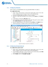
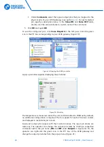
In the right panel, configure the I/O pins of A100 gateway that are connected
to external hardware (Figure 10). For each connected I/O pin, expand the
menu and select the logical pin in TRBOnet:
Specify the active level of the signal and other I/O pin settings.
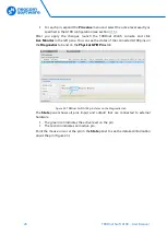
Note: For TRBOnet software to display the states of the A100 pins, configure
TRBOnet software as described in section
(page 24).
If a physical pin is not connected, leave it unassigned.
6.
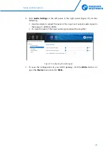
To save the configuration on your A100 gateway, click the
Write
button or
open the
Device
menu and click
Write
.
3.2
Non-MOTOTRBO Mode
To configure TRBOnet Swift A100 to operate in the non-MOTOTRBO mode, follow
the steps in Table 6.
Table 6: High-level steps to configure TRBOnet Swift A100 to operate in the non-MOTOTRBO mode
#
Step
Refer to:
1
Assemble the service cable.
3.2.1 Assembling the Service Cable
2
Install and connect the non-MOTOTRBO radio
3.2.2 Installing and Connecting the Radio
3
Configure the non-MOTOTRBO radio
4
Configure the A100 gateway
3.2.4 Configuring the A100 Gateway
3.2.1
Assembling the Service Cable
TRBOnet Swift A100 and a non-MOTOTRBO radio can be connected using the
service cable. To assemble the service cable, use a 6-pin connector plug (included in
the package contents), a wire kit, and a radio connector plug.
Note: The radio connector plug is not included in the package contents. Contact
the manufacturer of your radio or a sales representative to get the plug
compatible with the service connector of your radio.
To assemble the service cable:
1.
Connect the wires between the 6-pin connector plug and the radio connector
plug to implement the following required links:
Table 7: Service cable pinout
A100 6-pin connector
Radio connector
AUDIO OUT
EXT MIC AUDIO (TX AUDIO)
AUDIO IN
RX AUDIO
AUDIO GROUND
GND
PTT
PTT


