background image

Installing The Universal Receiver

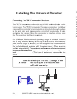
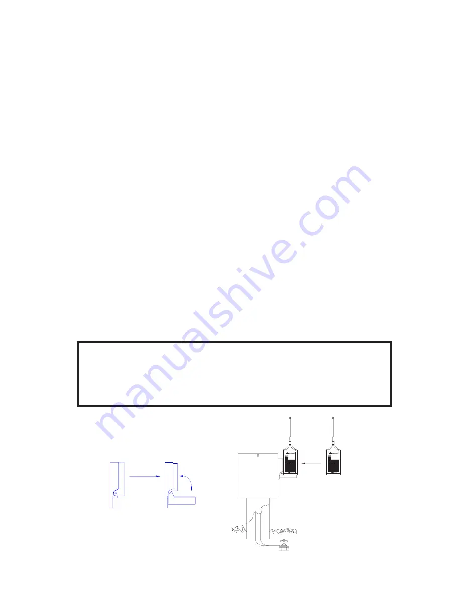
Connecting the TRC Commander Receiver

The TRC Commander works with any 24 VAC solenoid valve sprin-
kler system. The TRC Commander Receiver connects to individual
valves at the controller's terminal strip or directly to the valve wires
at the controller, and  bypasses the controller's functions by directly
activating the valves. Once the connector is installed, simply plug
the Receiver into the black receptical.

For locations where minimal operating range is needed, connect
the 8" whip antenna directly to the top of the Receiver. For locations
where more range is needed, use the magnetic base antenna and
the included tuned antenna with threaded base. (Other antenna
options are available). 

For maximum performance, all antennas should

be mounted far away from 

power transformers

electric motors

V.F.D.’s

and 

overhead powerlines

.


This type of equipment causes interfer-

ence.

WARNING!

Never

 connect directly to 110 VAC. Damage to the

receiver 

will

 occur, may be a fire hazard and

will void warranty.

22

        800-275-8558  www.remotecontroltech.com

1

2

3

4

5

6

7

8

9

AUTO

UP

TIME

AUTO

BACK

0

COMMANDER

REC

#

MV

OFF

VALVE

OFF

VALVE

ON

The Transmitter Key Pad

The Commander Transmitter keypad has an audible beep to
clearly indicate when a key is pressed. The Transmitter will
beep once when a Number Key or the Receiver Number Key is
pressed. The Transmitter will beep twice, with about two sec-
onds between beeps, after a transmit key is pressed for ("VALVE
ON", "VALVE OFF", "AUTO UP", "AUTO BACK", "M-V  OFF"
or "TIME"). The first beep indicates that the transmission is
starting, and the second beep indicates that transmission has
been completed.

7

        800-275-8558  www.remotecontroltech.com

Summary of Contents for Commander

Page 1: ...UNIVERSAL IRRIGATION REMOTE CONTROL Operation and Installation Manual COMMANDER ...

Page 2: ...th the limits for a Class A digital device pursuant to Part 15 of the FCC Rules The Trans mitter has been tested and found to comply with Part 95 Subpart E These limits are designed to provide reasonable protection against harmful inter ference when the equipment is operated in a commercial environment Canadian Certification 32151021261 2 800 275 8558 www remotecontroltech com Fa ...

Page 3: ... YEAR WARRANTY For three years from the date of purchase Remote Control Technol ogy Inc will repair or replace any of its products or parts to be found defective as to workmanship or materials This warranty does not extend to damage to a Remote Control Technology Inc product re sulting from misuse neglect or abuse improper installation or acci dent This warranty extends only to an original user of...

Page 4: ...h all 24VAC solenoid valve sprinkler systems and is capable of op erating 32 stations per controller This portable Receiver con nects easily with a permanent connector hard wired to the ter minal strip and a custom housing mounted on the controller for quick plug in Permanent Receiver Cards install easily and permanently into the controller Installing Permanent Receiver Cards allows all zones of t...

Page 5: ...e dipswitches offer 199 unique Receiver numbers Programmable security codes 9999 different security group codes Audible low power indicator Field replaceable 9 volt battery Master Valve disable key Pump Start Master Valve Permanent Receiver Cards are available for the following controllers Rain Bird ESP MC contact factory for SAT upgrades Rain Bird ESP LX Irritrol Dial MC Superior Sterling HIT Log...

Page 6: ...s automatically turned on or off unless MV Off has been pressed The Transmitter is designed for minimal power consumption to extend the life of the battery The Transmitter power is normally off Once any key has been pressed power is auto matically turned on for about ten seconds to allow your com mand sequence to be completed before the Transmitter auto matically turns the power off and erases the...

Page 7: ... pressed The Transmitter will beep once when a Number Key or the Receiver Number Key is pressed The Transmitter will beep twice with about two sec onds between beeps after a transmit key is pressed for VALVE ON VALVE OFF AUTO UP AUTO BACK M V OFF or TIME The first beep indicates that the transmission is starting and the second beep indicates that transmission has been completed 7 800 275 8558 www ...

Page 8: ...eps after the transmission beep indicates low battery power Replace with a new alkeline 9V battery Valve On Valve Off To turn a valve on press the desired zone number then press the Valve On key Pressing Valve Off will turn off the last zone acti vated When Valve Off is pressed by itself the current zone will turn off To turn that zone back on just press Valve On The Transmitter re members which v...

Page 9: ... mode station will not be automatically turned off when multiple mode stations are turned on If you try to turn on a seventh multiple mode valve the first multiple mode valve turned on will be automatically turned off WARNING Make sure your controller has adequate power to operate the number of multiple stations you intend to have on at one time Otherwise you may overload the circuit breaker at yo...

Page 10: ...will override the MV Off function It will also run the Master Valve Pump Start continuously To disable the Master Valve 0 0 TIME TIME 2 0 0 0 2 TIME 2 MV OFF 0 Time Duration You can set a time duration anywhere from two minutes to two hours Press three digits of time in the following format Hour Tens Minutes Minutes The range of allowed entries for time duration is from two minutes 002 to two hour...

Page 11: ...art Master Valve is auto matically activated when a valve station is turned on You can manu ally turn on the Pump Start Master Valve by pressing 99 Valve On IF YOU MANUALLY TURN ON THE PUMP START MASTER VALVE STATION YOU MUST MANUALLY TURN IT OFF AGAIN There is no default time with this function The Pump Start MV will stay on until 0 Valve Off or 99 Valve Off command is received Press the two digi...

Page 12: ...having to change pro gramming Pressing 9 then the desired number of days then Valve Off will program the Silent Running feature Silent Running Rain Off codes 90 Valve Off Infinite 91 Valve Off 1 Day 92 Valve Off 2 Days 93 Valve Off 3 Days 94 Valve Off 4 Days 95 Valve Off 5 Days 96 Valve Off 6 Days 97 Valve Off 7 Days 0 Valve Off Clear Pressing 0 then Valve Off will clear all and reset the Receiver...

Page 13: ...n r ...

Page 14: ... number dipswitch set Look on the back of the Receiver board you will see three boxes of dipswitches as shown in the photo Example 1 The dipswitches are ex posed on the circuit board on Permanent Receiver Cards Example 2 The Receiver switch set is the box on the far right The switches are read from right to left see below and are grouped in sets of four Adding the numbers of the depressed switches...

Page 15: ... Group Code Switch Set Receiver Switch Set EXAMPLE 2 Factory Default Permanent Receiver Card shown Group Code Switch Set is switched to Group Code 1 Receiver Switch Set is switched to Receiver 1 EXAMPLE 3 Permanent Receiver Card shown Group Code Switch Set is switched to Group Code 1 Receiver Switch Set is switched to Receiver 2 EXAMPLE 4 Permanent Receiver Card shown Group Code Switch Set is swit...

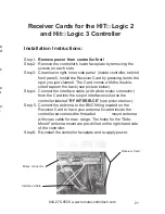
Page 16: ...here the ribbon cable was removed from Step 4 Plug the ribbon cable in the gray connector on Receiver Card Step 5 Connect the antenna to the BNC fitting on the Receiver Card or connect the external mount antenna with coax cable for max range Step 6 Re apply power to your conroller Receiver Card for the Rain Bird ESP MC Receiver Card Ribbon Cable Antenna Socket 16 800 275 8558 www remotecontroltech...

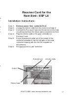
Page 17: ... cable was removed from Step 4 Plug the ribbon cable in the gray connector on Receiver Card Step 5 Route the antenna cable out of the bottom of the controller and attach it on the left side of the outer controller housing with the Vel Cro supplied on the antenna Step 6 Re apply power to your controller Receiver Card for the Rain Bird ESP LX Antenna Cable Receiver Card Ribbon Cable Socket 17 800 27...

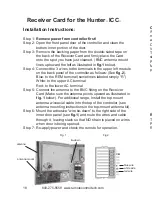
Page 18: ...abeled simply R White to the upper AC terminal Red to the lower AC terminal Step 5 Connect the antenna to the BNC fitting on the Receiver Card Make sure the antenna points upward as illustrated in fig 1 below For additional range install the top mount antenna w coaxial cable into the top of the controller see antenna mounting instructions in the top mount antenna kit Step 6 Mount the adhesive wire...

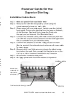
Page 19: ...ith white connector from the Card into the six pin molex connector on the back right hand side of controller face not illustrated here Step 5 Connect the antenna to the BNC fitting on the Receiver Card or connect the external mount antenna with coax cable for max range Step 6 Connect all of your field common wires to the silver screw terminal on the card then connect the black wire on on the Card ...

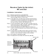
Page 20: ...o the six pin molex connector on the back right hand side of controller face not illustrated here Step 5 Connect the antenna to the BNC fitting on the Receiver Card or connect the external mount antenna with coax cable for max range Step 6 Connect all of your field common wires to the silver screw terminal on the card then connect the black wire on on the Card to a valve common terminal on the con...

Page 21: ... molex connector from the Card into the six pin interface socket on the controller labeled RF INTERFACE see picture below Step 5 Connect the antenna to the BNC fitting located on the Receiver Card to have your antenna located inside the controller or connect the threaded external mount antenna with coax cable for max range The holes for the Side Mount antenna mount are pre drilled on the right han...

Page 22: ...cal For locations where minimal operating range is needed connect the 8 whip antenna directly to the top of the Receiver For locations where more range is needed use the magnetic base antenna and the included tuned antenna with threaded base Other antenna options are available For maximum performance all antennas should be mounted far away from power transformers electric motors V F D s and overhe...

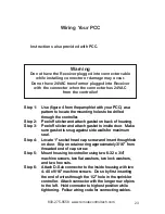
Page 23: ... the Receiver plugged into connector cable while installing connector or damage may occur Do not have 24VAC transformer plugged into Receiver with the connector when the connector has 24VAC from the controller Wiring Your PCC 23 800 275 8558 www remotecontroltech com Step 1 Use figure 4 from the pamphlet with your PCC as a pattern to locate the mounting holes to be drilled through the controller S...

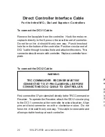
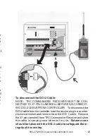
Page 24: ...I 2 Cable WARNING TRC COMMANDER RECEIVER MUST BE CONNECTED TO 37 PIN CLAMSHELL BEFORE CONNECTING DCI 2 CABLE TO CONTROLLER First connect the 37 pin clamshell directly to the TRC Commander Receiver To operate the Receiver attach the DCI 2 circular plug to the DCI 1 connector at the controller knockout location Align pins and twist connector on with a clockwise motion Do not force it in it should fi...

Page 25: ...R To disconnect the DCI 2 cable from the controller twist the circular plug in a counter clockwise motion and remove from the DCI 1 cable Remove the 37 pin clamshell from TRC Commander Receiver and store the cable in carrying case when not in use Extreme care should be taken with the DCI 2 cable to safeguard the in tegrity of its circuitry DCI 1 25 800 275 8558 www remotecontroltech com ...

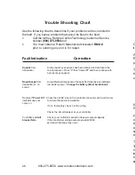
Page 26: ... continue with a proper key sequence Rapid beeps from An audible rapid sequence of beeps after transmission indicates transmitter or no low battery power Change the battery Must be alkeline sound Receiver Power On Check the 24VAC pins on the controller connector with a volt meter indicator does not to ensure that power is available come on If not thoroughly check out the wiring Check the circuit b...

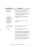
Page 27: ...he antenna is clear from obstructions The three feet immediately surrounding the antenna are the most crucial and should be kept clear of obstructions power lines or electrical conduits electric motors etc Keep the antenna as high as possible on the controller and avoid situations where the antenna can be shadowed by buildings or large metal structures Ensure that the Receiver s antenna is as far ...

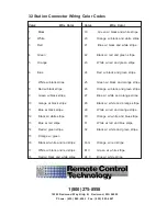
Page 28: ...k stripe 25 Green w black and orange stripe 8 Red w black stripe 26 Orange w black and green stripe 9 Green w black stripe 27 Blue w white and orange stripe 10 orange w black stripe 28 Black w white and orange stripe 11 Blue w black stripe 29 White w red and orange stripe 12 Black w white stripe 30 Orange w white and blue stripe 13 Blue w red stripe 31 White w red and blue stripe 14 Red w green st...

Reviews: