Alkaline
Transmitter uses one replacable
9V Alkaline
battery.
Getting To Know The Transmitter
The TRC Commander Transmitter sends a proprietary FM sig-
nal to the Commander Receiver(s) turning on or off selected
valves. With each valve activation or deactivation, the Pump
Start/Master Valve station, when used, is automatically turned
on or off unless "MV Off" has been pressed.
The Transmitter is designed for minimal power consumption
to extend the life of the battery. The Transmitter power is
normally off. Once any key has been pressed, power is auto-
matically turned on for about ten seconds to allow your com-
mand sequence to be completed before the Transmitter auto-
matically turns the power off and erases the command se-
quence from memory.
6
800-275-8558 www.remotecontroltech.com
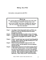
Step 1:
Use (figure 4 from the pamphlet with your PCC) as a
pattern to locate the mounting holes to be drilled
through the controller.
Step 2:
Peel off sticker and attach gasket on back of housing.
Step 3:
Peel off sticker and attach gasket to inside door. Make
sure gasket is snug against side walls for maximum
seal.
Step 4:
Locate 1" socket head cap screw and insert thoughhole
on door. Slip on retainer ring approximately 3/16" from
threaded end of cap screw.
Step 5:
Mount housing to controller using two 6-32 x 3/4"
machine screws, two flat washers, two lock washers,
and two hex nuts.
Step 6:
Attach D-Sub connector to the inside housing with two
4-40 x 9/16" machine screws. Do so by first inserting
the end of wires through the 1/2" hole in the sprinkler
controller. Attach connector with the longer row of pins
to the left. Hold connector to highest position while
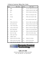
tightening. Follow wiring code for connecting cables.
Instructions also provided with PCC.
Warning
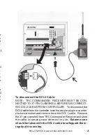
Do not have the Receiver plugged into connector cable
while installing connector or damage may occur.
Do not have 24VAC transformer plugged into Receiver
with the connector when the connector has 24VAC
from the controller!
Wiring Your PCC
23
800-275-8558 www.remotecontroltech.com
Step 1:
Use (figure 4 from the pamphlet with your PCC) as a
pattern to locate the mounting holes to be drilled
through the controller.
Step 2:
Peel off sticker and attach gasket on back of housing.
Step 3:
Peel off sticker and attach gasket to inside door. Make
sure gasket is snug against side walls for maximum
seal.
Step 4:
Locate 1" socket head cap screw and insert thoughhole
on door. Slip on retainer ring approximately 3/16" from
threaded end of cap screw.
Step 5:
Mount housing to controller using two 6-32 x 3/4"
machine screws, two flat washers, two lock washers,
and two hex nuts.
Step 6:
Attach D-Sub connector to the inside housing with two
4-40 x 9/16" machine screws. Do so by first inserting
the end of wires through the 1/2" hole in the sprinkler
controller. Attach connector with the longer row of pins
to the left. Hold connector to highest position while
tightening. Follow wiring code for connecting cables.


