4-3 Wiring Interface Connections
WARNING:
The following connection should only be performed by a qualified technician. Damage to equipment will occur if
connections are incorrect.
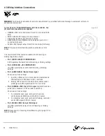
To interface the TOUGH GUN Reamer with the controller, five
(5) electrical connections are required:
l
ORANGE LEAD: Cycle Start output from PLC / controller (0.25
amp)
l
WHITE LEAD: 0 VDC supply 0.5 amp constant
l
RED LEAD: 24 VDC supply 0.5 amp constant
l
GREEN LEAD: Home Signal Jaws Unclamped input to PLC /
controller (0.25 amp)
l
BLACK LEAD: Sprayer output from PLC / controller (0.25 amp)
NOTE:
The pre-wired interface receptacle uses the above color
codes.
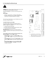
The circuit board of the reamer is capable of both sourcing or
sinking inputs and outputs:
l
Pin 1 (WHITE LEAD): 0 CONSTANT VDC
0 VDC operates the board for both Sourcing or Sinking settings
l
Pin 2 (RED LEAD): +24 CONSTANT VDC
+24 VDC operates the board for both Sourcing or Sinking
settings
l
Pin 3 (GREEN LEAD): Reamer Home signal
Choose one of two settings:
1. Sourcing - When unit is in Home position, reamer sends
HIGH signal (+24 VDC) back to PLC / controller
2. Sinking - When unit is in Home position, reamer sends
LOW signal (0 VDC) signal back to PLC / controller
l
Pin 4 (ORANGE LEAD): Cycle Start signal
(signal should be a
pulse with a maximum of 0.5 seconds in duration)
Choose one of two settings:
1. To initiate the ream cycle, set board to Sourcing,
controller sends HIGH signal (+24 VDC) to reamer
2. To initiate the ream cycle, set board to Sinking, controller
sends LOW signal (0 VDC) to reamer
l
Pin 5 (BLACK LEAD): Sprayer Start signal
+24 VDC operates the sprayer for both Sourcing or Sinking
settings
NOTE:
See section 4-4 Inversing Circuit Board Logic on page 15 for
more information.
Figure 4-A
14
OM-TT3-1.4

