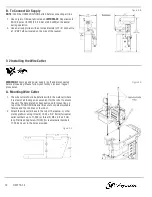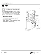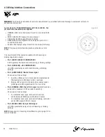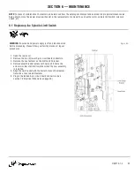
6-2 Replacing the Clamp Limit Switch
WARNING:
Ensure air and power supply is off and disconnected
before proceeding. Please follow your facility's lockout / tagout
procedures.
1. Remove the top plate of the reamer.
2. Open the rear cover.
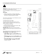
3. Disconnect the 3-pin connector from the lower right corner of
the circuit board.
4. Loosen the screws and remove the wires from the circuit
board connector. Note the wire colors and their positions
within the connector.
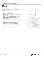
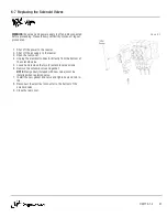
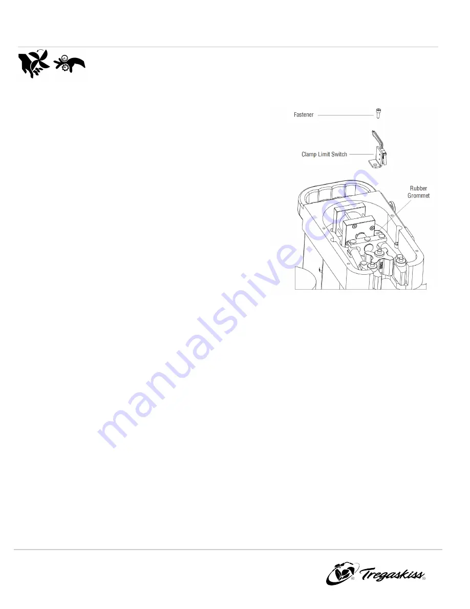
5. Remove the clamp limit switch fastener and remove assembly
(pull the wires through the grommet).
6. Slide the two wires through the grommet into the TOUGH
GUN Reamer.
7. Fasten the new clamp limit switch into position.
8. Install the two wires into the new keyed circuit board
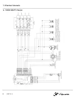
connector (see section 7-2 Electrical Schematic on page 30).
9. Clip the circuit board connector into location on the circuit
board.
10. Reinstall the top plate and close the rear cover.
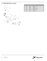
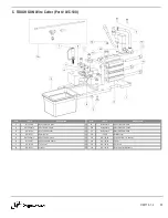
Figure 6-B
24
OM-TT3-1.4

