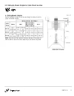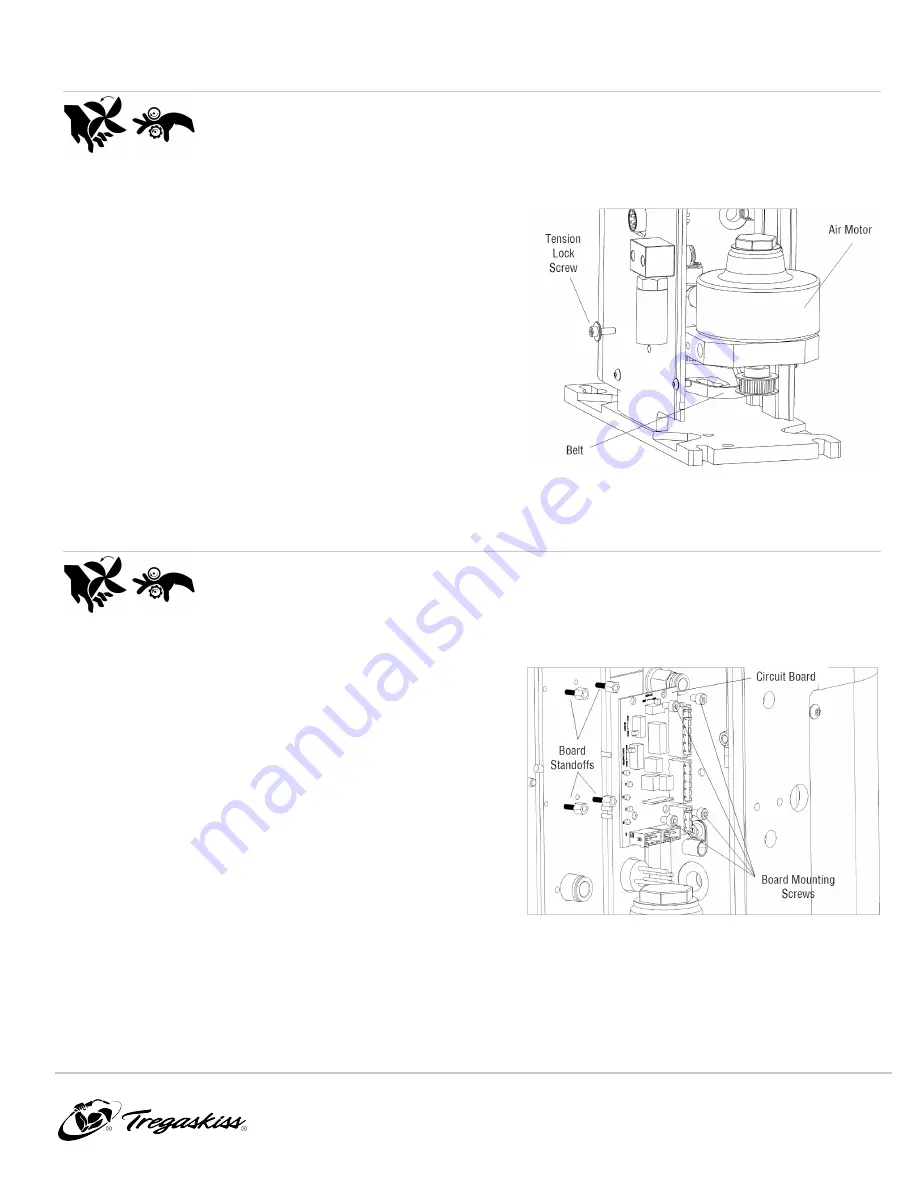
6-3 Replacing the Air Motor
WARNING:
Ensure air and power supply is off and disconnected
before proceeding. Please follow your facility's lockout / tagout
procedures.
1. Open the rear cover, or remove it completely by removing the
five (5) BHCS using a 3 mm Allen wrench.
2. Remove the tension lock screw located on the side of the
reamer frame.
3. Push the motor in to release belt tension, and slide the belt
off the front pulley at the same time.
4. Disengage belt from the rear pulley.
5. Release the air lines from the quick disconnect air fittings at
the front of the motor.
6. Pull the motor out.
IMPORTANT:
Be careful not to lose the
belt tension spring.
7. Reverse the order of the above steps for reassembly.
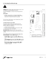
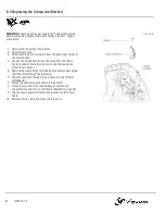
Figure 6-C
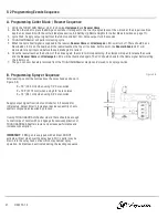
6-4 Replacing the Circuit Board
WARNING:
Ensure air and power supply is off and disconnected
before proceeding. Please follow your facility's lockout / tagout
procedures.
1. Open the rear cover.
2. Being careful not to damage the wiring. Disconnect all wiring
and remove the connectors from the circuit board.
3. Remove the fasteners which secure the circuit board to the
standoffs.
IMPORTANT:
Ensure all four (4) standoffs are still
attached to the frame.
4. Remove the board from the unit and install the replacement
in the same position.
5. Once located in the proper position, secure the circuit board
by tightening the four fasteners.
6. Reconnect all wiring and reset sink/source switches to match
the configuration of the board that was removed.
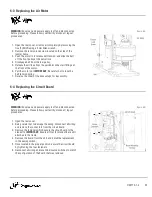
Figure 6-D
OM-TT3-1.4
25


