background image

l

Be alert that welding sparks and hot materials from welding
can easily go through small cracks and openings to adjacent
areas.

l

Watch for fire, and keep a fire extinguisher nearby.

l

Be aware that welding on a ceiling, floor, bulkhead, or
partition can cause fire on the hidden side.

l

Do not cut or weld on tire rims or wheels. Tires can explode
if heated. Repaired rims and wheels can fail. See OSHA 29
CFR 1910.177 listed in Principal Safety Standards.

l

Do not weld on containers that have held combustibles, or
on closed containers such as tanks, drums, or pipes unless
they are properly prepared according to AWS F4.1 and AWS
A6.0 (see Principal Safety Standards).

l

Do not weld where the atmosphere can contain flammable
dust, has, or liquid vapors (such as gasoline).

l

Connect work cable to the work as close to the welding area
as practical to prevent welding current from traveling long,
possibly unknown paths and causing electric shock, sparks,
and fire hazards.

l

Do not use welder to thaw frozen pipes.

l

Remove stick electrode from holder or cut off welding wire
at contact tip when not in use.

l

Wear body protection made from durable, flame-resistant
material (leather, heavy cotton, wool). Body protection
includes oil-free clothing such as leather gloves, heavy shirt,
cuffless trousers, high shoes, and a cap.

l

Remove any combustibles, such as a butane lighter or
matches, from your person before doing any welding.

l

After completion of work, inspect area to ensure it is free of
sparks, glowing embers, and flames.

l

Use only correct fuses or circuit breakers. Do not oversize or
bypass them.

l

Follow requirements in OSHA 1910.252 (a) (2) (iv) and NFPA
51B for hot work and have a fire watcher and extinguisher
nearby.

l

Read and understand the Safety Data Sheets (SDSs) and the
manufacturer's instructions for adhesives, coatings,
cleaners, consumables, coolants, degreasers, fluxes, and
metals.

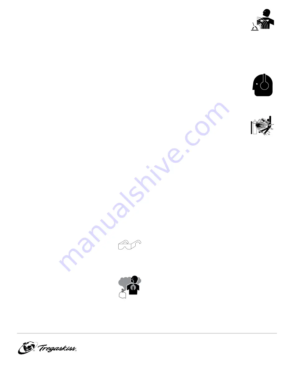
FLYING METAL or DIRT can injure eyes.

l

Welding, chipping, wire brushing, and
grinding cause sparks and flying metal. As
welds cool, they can throw off slag.

l

Wear approved safety glasses with side shields even under
your welding helmet.

BUILDUP OF GAS can injure or kill.

l

Shut off compressed gas supply when not in
use.

l

Always ventilate confined spaces or use approved air-
supplied respirator.

ELECTRIC AND MAGNETIC FIELDS (EMF) can
affect Implanted Medical Devices.

l

Wearers of Pacemakers and other Implanted
Medical Devices should keep away.

l

Implanted Medical Device wearers should consult their
doctor and the device manufacturer before going near arc
welding, spot welding, gouging, plasma arc cutting, or
induction heating operations.

NOISE can damage hearing.

Noise from some processes or equipment can
damage hearing.

l

Wear approved ear protection if noise level is
high.

CYLINDERS can explode if damaged.

Compressed gas cylinders contain gas under high
pressure. If damaged, a cylinder can explode.
Since gas cylinders are normally part of the
welding process, be sure to treat them carefully.

l

Protect compressed gas cylinders from excessive heat,
mechanical shocks, physical damage, slag, open flames,
sparks, and arcs.

l

Install cylinders in an upright position by securing to a
stationary support or cylinder rack to prevent falling or
tipping.

l

Keep cylinders away from any welding or other electrical
circuits.

l

Never drape a welding torch over a gas cylinder.

l

Never allow a welding electrode to touch any cylinder.

l

Never weld on a pressurized cylinder – explosion will result.

l

Use only correct compressed gas cylinders, regulators,
hoses, and fittings designed for the specific application;
maintain them and associated parts in good condition.

l

Turn face away from valve outlet when opening cylinder
valve. Do not stand in front of or behind the regulator when
opening the valve.

l

Keep protective cap in place over valve except when cylinder
is in use or connected for use.

l

Use the proper equipment, correct procedures, and
sufficient number of persons to lift, move, and transport
cylinders.

l

Read and follow instructions on compressed gas cylinders,
associated equipment, and Compressed Gas Association
(CGA) publication P-1 listed in Principal Safety Standards.

OM-TT3-1.4

3

Summary of Contents for TOUGH GUN TT3 Reamer

Page 1: ...above Robotic Nozzle Cleaning Station MIG GMAW Welding Peripheral Tregaskiss com TechnicalSupport 1 855 MIGWELD 644 9353 US Canada 1 519 737 3000 International August 2020 OM TT3 1 4 TOUGH GUN TT3 Re...

Page 2: ...e to the best of our knowledge at the time of printing Please reference Tregaskiss com for updated material For customer support and special applications please call the Tregaskiss Customer Service De...

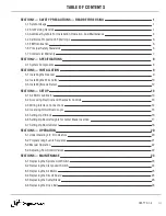
Page 3: ...P 13 4 1 Air Motor Lubricator 13 4 2 Accessing Electrical and Pneumatic Controls 13 4 3 Wiring Interface Connections 14 4 4 Inversing Circuit Board Logic 15 4 5 Setting Up V Block 16 4 6 Setting Up No...

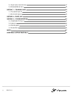
Page 4: ...7 TECHNICAL DATA 29 7 1 Pneumatic Diagrams 29 7 2 Electrical Schematic 30 SECTION 8 PARTS LIST 31 SECTION 9 TROUBLESHOOTING 34 9 1 TOUGH GUN TT3 Reamer 34 9 2 Lubricator 35 9 3 Filter Regulator 35 9...

Page 5: ...ire reel drive roll housing and all metal parts touching the welding wire are electrically live Incorrectly installed or improperly grounded equipment is a hazard l Do not touch live electrical parts...

Page 6: ...the manufacturer s instructions for adhesives coatings cleaners consumables coolants degreasers fluxes and metals l Work in a confined space only if it is well ventilated or while wearing an air supp...

Page 7: ...d flying metal As welds cool they can throw off slag l Wear approved safety glasses with side shields even under your welding helmet BUILDUP OF GAS can injure or kill l Shut off compressed gas supply...

Page 8: ...G PARTS can injure l Keep away from moving parts l Keep away from pinch points such as drive rolls WELDING WIRE can injure l Do not press gun trigger until instructed to do so l Do not point gun towar...

Page 9: ...FCC about interference stop using the equipment at once l Have the installation regularly checked and maintained l Keep high frequency source doors and panels tightly shut keep spark gaps at correct s...

Page 10: ...http www aws org or purchased from Global Engineering Documents phone 1 877 413 5184 website www global ihs com Safe Practices for the Preparation of Containers and Piping for Welding and Cutting Ame...

Page 11: ...replace or refund the purchase price of non conforming product Product found not defective will be returned to the Buyer after notification by Customer Service Tregaskiss makes no other warranty of a...

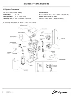
Page 12: ...e 24 VDC Min 80 to max 100 psi 5 5 to 7 0 bar at 16 CFM 450 LPM Operating Voltage 10 of rated voltage Air Motor at min air requirement Power Consumption Max wattage in operation 5 3 W Stall torque at...

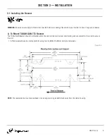
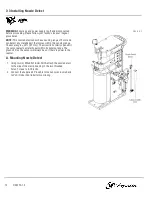
Page 13: ...TOUGH GUN TT3 Reamer The TOUGH GUN Reamer should be installed within the weld cell where it is clear of all tooling and convenient for the robot to access the unit 1 Affix the reamer base to a sturdy...

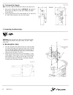
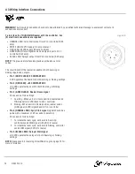
Page 14: ...e follow your facility s lockout tagout procedures A Mounting Wire Cutter 1 The wire cutter should be installed within the weld cell where it is clear of all tooling and convenient for the robot to ac...

Page 15: ...red air IMPORTANT Requirements 80 100 psi at 16 CFM 5 5 7 0 bar at 450 LPM at the wire cutter 2 Use an air supply line with an inside diameter of 1 4 and connect to 1 8 female NPT inlet located on the...

Page 16: ...e The accuracy is 2 0 1 mm The circuit is normally open until the sensor detects a metallic part within its sensing range The green LED on the sensor will always be on if there is power to the reamer...

Page 17: ...grade hydraulic oil with a viscosity rating of 150 VC 15 20 SAE 5W 4 2 Accessing Electrical and Pneumatic Controls WARNING Ensure power supply is off and disconnected before proceeding Please follow y...

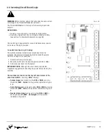
Page 18: ...erates the board for both Sourcing or Sinking settings l Pin 2 RED LEAD 24 CONSTANT VDC 24 VDC operates the board for both Sourcing or Sinking settings l Pin 3 GREEN LEAD Reamer Home signal Choose one...

Page 19: ...trical and Pneumatic Controls on page 13 for directions 1 Disconnect from power supply 2 Move the switches to the desired positions SRC or SNK 3 Connect power back into the reamer IMPORTANT NOTE Altho...

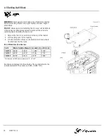
Page 20: ...our 4 cover screws at the top of the reamer 2 Lift the clamp cover off completely 3 Lift and rotate the v block so the desired size faces outward from between the front jaws See V Block Size Chart bel...

Page 21: ...404 3 404 20 404 26 404 30 404 32 D ATSH D ATTH 454 1 RCT 13 3 4 19 05 mm 0 110 Below 2 79 mm Below 0 375 9 53 mm 0 466 11 84 mm RCT 01 5 8 15 88 mm 0 030 0 762 mm 0 225 5 72 mm 0 716 18 19 mm RCT 04...

Page 22: ...nto position beside the nozzle detect sensor 2 Measure the distance from the tangent face of the nozzle to the face of the nozzle detect sensor ensuring that it is 3 mm 1 mm 3 The ring crimp on the no...

Page 23: ...the nozzle keeping the retaining head on 3 Move robot back to the programmed position that was used in Step 1 above The yellow light should not illuminate indicating that there is no nozzle on the to...

Page 24: ...mps are open and the lower limit switch is working properly CLAMP MOTOR VALVE SHORT OFF Indicates short with clamp or motor valve when ON REAMER AHEAD OFF Indicates that the TOUGH GUN Reamer has reach...

Page 25: ...ill open to release the nozzle and the Reamer Home and Unclamped L E D s will be illuminated again The PLC should check for the Home signal before letting the robot move 7 The gun can now be safely re...

Page 26: ...feed rate is dependent on the amount of spatter accumulated If a smaller amount of spatter accumulates the feed rate can be set faster A feed rate that is set too fast may stall the motor or damage t...

Page 27: ...and disconnected before proceeding Please follow your facility s lockout tagout procedures 1 Open the rear cover 2 Remove the two 2 lower 3 pin circuit board connectors 3 Remove the one fastener on th...

Page 28: ...circuit board connector Note the wire colors and their positions within the connector 5 Remove the clamp limit switch fastener and remove assembly pull the wires through the grommet 6 Slide the two wi...

Page 29: ...on spring 7 Reverse the order of the above steps for reassembly Figure 6 C 6 4 Replacing the Circuit Board WARNING Ensure air and power supply is off and disconnected before proceeding Please follow y...

Page 30: ...r supply lines This prevents slipping while trying to remove the cutter blade Figure 6 E B To Install the Cutter Blade 1 The cutter blade is installed by threading it clockwise into the top of the spi...

Page 31: ...he rear cover 4 Unplug the electrical connector directly from the bottom of the solenoid valve 5 Loosen and remove the two 2 solenoid valve screws 6 Remove the solenoid valve and gasket NOTE New gaske...

Page 32: ...block reamer clamp jaw and spindle seal with a brush or with compressed air to eliminate blockages CLEAN Wipe clean any debris from the Nozzle Detect Proximity Sensor MONTHLY CHECK That the belt tensi...

Page 33: ...SECTION 7 TECHNICAL DATA 7 1 Pneumatic Diagrams A TOUGH GUN TT3 Reamer B TOUGH GUN TT3 Reamer with Lubricator OM TT3 1 4 29...

Page 34: ...7 2 Electrical Schematic A TOUGH GUN TT3 Reamer 30 OM TT3 1 4...

Page 35: ...acer 21 TT3 001 50 Reamer sprayer subassembly 7 TR 2321 Limit switch assembly 22 TR 2310 Reamer circuit board 8 See section 4 5 4 sided v block 23 RR 1320 Reservoir 9 TR 2661 Spindle seal 24 R 2241 1...

Page 36: ...bly ITEM PART DESCRIPTION 1 TT3 001 5 Sprayer steel line kit 2 RR 1320 Reservoir 3 TT3E 500 20 Sprayer check valve 4 TS 500 15 Spray block with fittings 5 Not Sellable 1 4 sprayer hose 6 SR 500 1 Spra...

Page 37: ...le M8x1 25x55mm SCHCS 3 WC 100 20 Wire catcher basket 11 Not Sellable M8x1 25x50mm SHCS 4 WC 100 27 Backing plate 12 TR 2221 Breather vent 5 Not Sellable M3x0 5x12mm SHCS 13 WC 100 24 Solenoid valve T...

Page 38: ...Reconnect power 4 Broken cutter 1 Improper cutter being used 2 Flow control valve set too fast 3 Gun improperly aligned in TOUGH GUN Reamer 1 Repair or replace damaged components 2 Adjust feed rate a...

Page 39: ...correctly as shown in manual 2 Remove the valve guide to clean the valve and valve seat 2 Set pressure does not return to zero when pressure handle is loosened 1 Foreign materials caught in the valve...

Page 40: ...D is illuminated 1 Nozzle not close enough to sensor 1 Confirm that robot position is at the correct distance from the sensor see section 4 7 Setting Up Nozzle Detect on page 18 3 Both LEDs are always...

Page 41: ...NOTES 37 OM TT3 1 4...

Page 42: ...mmediate access to Tregaskiss com TechnicalSupport Scan to view the TOUGH GUN TT3 Reamer Owner s Manual Scan to view the TOUGH GUN TT3 Reamer Spec Sheet Scan to view the TOUGH GUN Wire Cutter Owner s...

Reviews: