7-5 Setting Up V-Block
WARNING:
Ensure power and air supply are off and disconnected
before proceeding. Please follow your facility's lockout / tagout
procedures.
PRO TIP:
Removing and/or installing the top cover will be difficult if
the air has not been disconnected. Disconnect the air prior to
removing and/or installing the top cover.
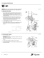
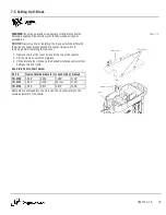
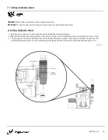
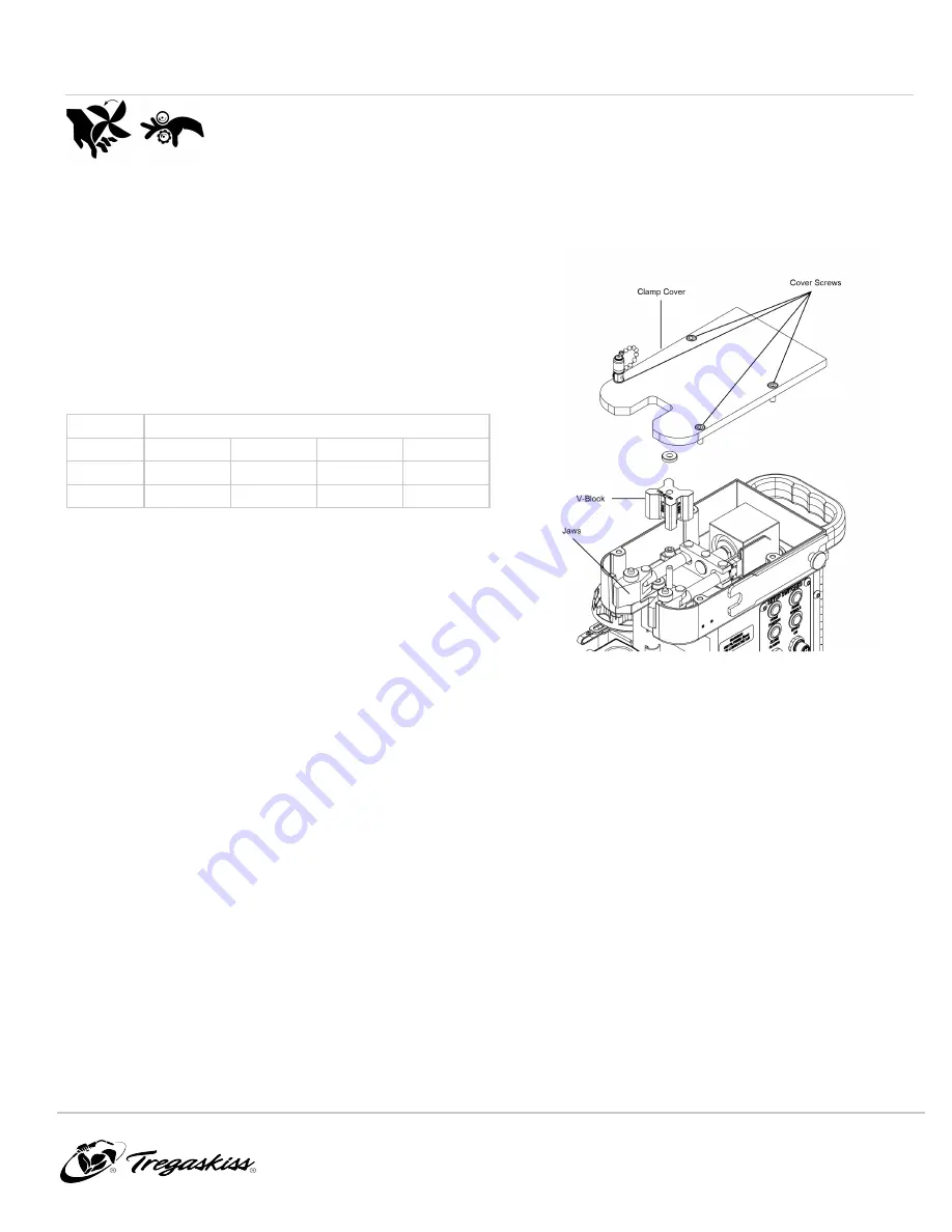
1. Remove the four (4) cover screws at the top of the reamer.
2. Lift the clamp cover off completely.
3. Lift and rotate the v-block so the desired size faces outward from
between the front jaws.
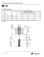
See V-Block Size Chart below:
Part #
Nozzle Outside Diameter for each side of V-block
TR-2150
0.850"
0.938"
1.062"
1.106"
TR-2161
0.830"
0.978"
25 mm
1.125"
TR-2162
0.780"
0.813"
0.875"
1.000"
Numbers are stamped into the v-blocks. The number refers to the
outside diameter of the nozzle.
Figure 7-C
OM-TT4A-1.0
19

