background image

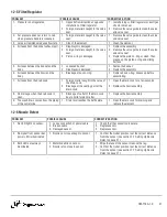
12-5 Filter/Regulator

PROBLEM

POSSIBLE CAUSE

CORRECTIVE ACTION

 1.  Pressure is not regulated.

 1.  Opposite flow direction or opposite 

installation of filter/regulator.

 2.  Foreign materials caught in the valve 

seat.

 1.  Install piping or filter/regulator correctly as 

shown in manual.

 2.  Remove the valve guide to clean the valve 

and valve seat.

 2.  Set pressure does not return to zero 

when pressure handle is loosened.

 1.  Foreign materials caught in the valve 

seat.

 1.  Remove the valve guide to clean the valve 

and valve seat.

 3.  Large air resistance reduces flow rate.

 1.  Clog of the element.

 1.  Clean the element.

 4.  Air leaks from the bonnet exhaust port.

 1.  Diaphragm is damaged.
 2.  Foreign materials caught in the valve 

seat.

 3.  Piston o-ring is damaged.

 1.  Replace the assembly.
 2.  Remove the valve guide to clean the valve 

and valve seat.

 3.  Replace the piston o-ring or clean. Then 

grease up the piston o-ring and sliding 
surface.

 5.  Air leaks between the bonnet and the 

body.

 1.  Loosened bonnet.
 2.  Diaphragm is damaged.

 1.  Fasten the bonnet.
 2.  Replace the assembly.

 6.  Air leaks between the bowl and the 

body.

 1.  Breakage of bowl o-ring.

 1.  Replace bowl o-ring. Grease up before 

assembling.

 7.  Air leaks from the drain cock.

 1.  Foreign matter caught in the valve of 

the drain cock.

 2.  Breakage of the seating part of the 

drain cock.

 1.  Open the drain cock for a few seconds.

 2.  Replace the bowl assembly.

 8.  No drainage when the drain cock is 

open.

 1.  Blockage of outlet of the drain cock 

due to solid foreign matter.

 1.  Replace the bowl assembly.

 9.  Too much drain comes from the piping 

of the outlet side.

 1.  Drain level reaches the baffle plate.

 1.  Open the drain cock for draining and 

replace the element.

12-6 Nozzle Detect

PROBLEM

POSSIBLE CAUSE

CORRECTIVE ACTION

 1.  No LED lights on sensor.

 1.  Loose connection of power cable.
 2.  Broken cable.
 3.  Damaged sensor.

 1.  Check that the connection is secure.
 2.  Replace sensor.
 3.  Replace sensor.

 2.  No signal from sensor but 

power LED is illuminated.

 1.  Nozzle not close enough to sensor.

 1.  Confirm that robot position is at the correct distance 

from the sensor (see section 7-7 Setting Up Nozzle 
Detect on page 21)
.

 3.  Both LEDs are always 

illuminated.

 1.  Metallic debris on sensor.
 2.  Nozzle is too close to sensor.

 1.  Wipe the face of the sensor clean with a rag.
 2.  Confirm that robot position is at the correct distance 

from the sensor (see section 7-7 Setting Up Nozzle 
Detect on page 21)
.

OM-TT4A-1.0

41

Summary of Contents for TOUGH GUN TT4A

Page 1: ...Nozzle Cleaning Station MIG GMAW Welding Peripheral Tregaskiss com TechnicalSupport 1 855 MIGWELD 644 9353 US Canada 1 519 737 3000 International September 2021 OM TT4A 1 0 TOUGH GUN TT4A Reamer OWNER S MANUAL ...

Page 2: ...askiss com for updated material For customer support and special applications please call the Tregaskiss Customer Service Department at 1 855 MIGWELD 644 9353 US Canada or 1 519 737 3000 International fax 1 519 737 1530 or email at cs itwmig com Our trained Customer Service Team is available between 8 00 a m and 5 30 p m EST and will answer your product application or repair questions Tregaskiss m...

Page 3: ...so de símbolos 7 3 2 Peligros en soldadura de arco 7 3 3 Advertencias de la Proposición 65 del estado de California 9 3 4 Estándares principales de seguridad 9 3 5 Información sobre los campos electromagnéticos EMF 9 SECTION 4 PRODUCT WARRANTY 10 4 1 Product Warranty 10 SECTION 5 SPECIFICATIONS 11 5 1 System Components 11 SECTION 6 INSTALLATION 12 6 1 Installing the Reamer 12 6 2 Installing the Wi...

Page 4: ...cing the Solenoid Valves 29 9 6 Replacing the Circuit Board 29 9 7 Removing the Spray Containment Unit 30 9 8 Replacing the Cutter Blade 31 9 9 Removing the Anti Spatter Fluid Reservoir 32 9 10 Scheduled Maintenance 34 SECTION 10 TECHNICAL DATA 35 10 1 Pneumatic Diagrams 35 10 2 Electrical Schematic 36 SECTION 11 PARTS LIST 37 SECTION 12 TROUBLESHOOTING 39 12 1 TOUGH GUN TT4A Reamer 39 12 2 Lubric...

Page 5: ... When you see the symbol watch out and follow the related instructions to avoid the hazard The safety information given below is only a summary of the more complete safety information found in section 1 4 Principal Safety Standards on page 3 Read and follow all Safety Standards Only qualified persons should install operate maintain and repair this equipment A qualified person is defined as one who...

Page 6: ...ng or servicing unit Read the safety information at the beginning of the Manual and in each section l Use only genuine replacement parts from the manufacturer l Perform installation maintenance and service according to the Owner s Manuals industry standards and national state and local codes 2 OM TT4A 1 0 ...

Page 7: ...Safety and Health Standards for General Industry Title 29 Code of Federal Regulations CFR Part 1910 177 Subpart N Part 1910 Subpart Q and Part 1926 Subpart J Website www osha gov SR7 2020 02 1 5 EMF Information Electric current flowing through any conductor causes localized electric and magnetic fields EMF The current from arc welding and allied processes including spot welding gouging plasma arc ...

Page 8: ...oudage à l arc Les symboles présentés ci après sont utilisés tout au long du présent manuel pour attirer votre attention et identifier les risques de danger Lorsque vous voyez un symbole soyez vigilant et suivez les directives mentionnées afin d éviter tout danger Les onsignes de sécurité présentées ci après ne font que résumer les informations contenues dans la section 2 4 Principales normes de s...

Page 9: ...nger inhérent au bruit LIRE LES INSTRUCTIONS l Lire et appliquer les instructions sur les étiquettes et le mode d emploi avant l installation l utilisation ou l entretien de l appareil Lire les informations de sécurité au début du manuel et dans chaque section l N utiliser que les pièces de rechange recommandées par le constructeur l Effectuer l installation l entretien et toute intervention selon...

Page 10: ...art 1910 Subpart Q and Part 1926 Subpart J Website www osha gov SR7_fre 2020 02 2 5 Informations relatives aux CEM Le courant électrique qui traverse tout conducteur génère des champs électromagnétiques CEM à certains endroits Le courant issu d un soudage à l arc et de procédés connexes y compris le soudage par points le gougeage le découpage plasma et les opérations de chauffage par induction cré...

Page 11: ...éste manual para llamar la atención e identificar a peligros posibles Cuando usted vea este símbolo tenga cuidado y siga a las instrucciones relacionadas para evitar el peligro La información de seguridad dada abajo es solamente un resumen de la información más completa de seguridad que se encuentra de seguridad de sección 3 4 Estándares principales de seguridad on page 9 Lea y siga todas los está...

Page 12: ...STRUCCIONES l Lea y siga cuidadosamente las instrucciones contenidas en todas las etiquetas y en el Manual del usuario antes de instalar utilizar o realizar tareas de mantenimiento en la unidad Lea la información de seguridad incluida en la primera parte del manual y en cada sección l Utilice únicamente piezas de reemplazo legítimas del fabricante l Los trabajos de instalación y mantenimiento debe...

Page 13: ... 3 5 Información sobre los campos electromagnéticos EMF La corriente que fluye a través de un conductor genera campos eléctricos y magnéticos EMF localizados La corriente del arco de soldadura y otras técnicas afines como la soldadura por puntos el ranurado el corte por plasma y el calentamiento por inducción genera un campo EMF alrededor del circuito de soldadura Los campos EMF pueden interferir ...

Page 14: ...all pay Tregaskiss for all warranty claim costs incurred by Tregaskiss including inspection labor parts testing scrap and freight due to warranty claims submitted by Purchaser which are not covered by Tregaskiss warranty l Bernard BTB Semi Automatic Air Cooled MIG Guns 1 year Lifetime warranty on straight handles straight handle switches and rear strain relief l Bernard W Gun and T Gun Semi Automa...

Page 15: ...rated voltage Air Motor at min air requirement Power Consumption Max wattage in operation 5 3 W Stall torque at 80 psi 5 5 bar 83 in lbs 9 4 Nm Anti Spatter Requirements Water based anti spatter liquid must be used Oil based anti spatter solution will compromise performance 5 1 System Components For complete parts list please see Section 11 Parts List on page 37 OM TT4A 1 0 11 ...

Page 16: ...r should be installed within the weld cell where it is clear of all tooling and convenient for the robot to access the unit 1 Affix the reamer base to a sturdy platform using four 4 M10x1 5x25 mm bolts provided Figure 6 A NOTE The reamer can be mounted on an angle no more than 45 and can be mounted overhead only by using the multi feed adapter kit part TT4 MF 100 Ensure debris falls away from the ...

Page 17: ...ing air line 1 Use only dry filtered lubricated air IMPORTANT Requirements 80 100 psi at 16 CFM 5 5 7 0 bar at 450 LPM at the reamer during operation 2 Use an air supply line with an inside diameter of 3 8 Connect to a 1 4 NPT T fitting located on the side of the reamer OM TT4A 1 0 13 ...

Page 18: ...he same three 3 M6x1 0x20 mm Socket Head Cap Screws SHCS that are securing the clamp housing cover onto the reamer see Figure 6 D 3 If mounting a WC 100 wire cutter old style to the reamer use three 3 M6x1 0x25 mm SHCS 4 Thread the M12 connector into the 4 Pin receptacle labeled Wire Cutter located on the Setup Switch plate on the side of the reamer Figure 6 C Figure 6 D B Connecting Air Supply 1 ...

Page 19: ...he accuracy is 2 0 1 mm The circuit is normally open until the sensor detects a metallic part within its sensing range The green LED on the sensor will always be on if there is power to the reamer A Mounting Nozzle Detect 1 Using two 2 M3x0 5x16 mm SHCS attach the nozzle detect to the side of the clamp housing in the two threaded holes Torque to 8 10 in lbs 2 Connect the nozzle detect cable into t...

Page 20: ...y rating of 150 VC 15 20 SAE 5W 7 2 Accessing Electrical and Pneumatic Controls WARNING Ensure power supply is off and disconnected before proceeding Please follow your facility s lockout tagout procedures To access the electronic circuit board for installation or service for the TOUGH GUN Reamer 1 Loosen the two 2 M5 thumb screws to open the hinged rear access door It is not necessary to fully re...

Page 21: ...erates the board for both Sourcing or Sinking settings l Pin 2 RED LEAD 24 CONSTANT VDC 24 VDC operates the board for both Sourcing or Sinking settings l Pin 3 GREEN LEAD Reamer Home signal Choose one of two settings 1 Sourcing When unit is in Home position reamer sends HIGH signal 24 VDC back to PLC controller 2 Sinking When unit is in Home position reamer sends LOW signal 0 VDC signal back to PL...

Page 22: ...switch from Sourcing to Sinking The switches located inside the rear access door must be accessed See section 7 2 Accessing Electrical and Pneumatic Controls on page 16 for directions 1 Disconnect from power supply 2 Move the switches to the desired positions SRC or SNK 3 Connect power back into the reamer The switches are located on the top left hand corner of the circuit board SRC Sourcing SNK S...

Page 23: ...stalling the top cover 1 Remove the four 4 cover screws at the top of the reamer 2 Lift the clamp cover off completely 3 Lift and rotate the v block so the desired size faces outward from between the front jaws See V Block Size Chart below Part Nozzle Outside Diameter for each side of V block TR 2150 0 850 0 938 1 062 1 106 TR 2161 0 830 0 978 25 mm 1 125 TR 2162 0 780 0 813 0 875 1 000 Numbers ar...

Page 24: ...er blade insertion Retaining Head Gas Diffuser Cutter Blade Nozzle 404 20 404 26 404 30 404 32 D ATSH D ATTH RCT 13 3 4 19 05 mm 0 375 9 53 mm RCT 01 5 8 15 88 mm 0 225 5 72 mm RCT 04 1 2 12 7 mm 0 125 3 18 mm NOTE Using the top of the reamer as the datum the base of the nozzle will either be above this datum depending on the nozzle configuration Figure 7 D 20 OM TT4A 1 0 ...

Page 25: ...into position beside the nozzle detect sensor 2 Measure the distance from the tangent face of the nozzle to the face of the nozzle detect sensor ensuring that it is 3 mm 1 mm 3 The ring crimp on the nozzle should be in line with the center of the sensor yellow circle portion on the face of the sensor The vertical distance between the top of the reamer clamp housing and the base of the nozzle outer...

Page 26: ... the nozzle keeping the retaining head on 3 Move robot back to the programmed position that was used in Step 1 above The yellow light should not illuminate indicating that there is no nozzle on the gun NOTE Adjustments may be necessary if you are not using genuine Tregaskiss consumables The setup distances may change but the procedure does not change Figure 7 F Figure 7 G Figure 7 H 22 OM TT4A 1 0...

Page 27: ...mps are open and the lower limit switch is working properly CLAMP MOTOR VALVE SHORT OFF Indicates short with clamp or motor valve when ON REAMER AHEAD OFF Indicates that the TOUGH GUN Reamer has reached full upper stroke and the limit pin is activating the upper limit switch Unless the Reamer gets stuck at the top this L E D will only be ON for a split second before the unit begins to retract and ...

Page 28: ...pen to release the nozzle and the Reamer Home and Unclamped L E D s will be illuminated again The PLC should check for the Home signal before letting the robot move 7 The gun can now be safely removed from the TOUGH GUN Reamer clamps and moved to its spray position B Programming Sprayer Sequence Important Note Do not use oil based anti spatter solution as this will compromise performance 1 After r...

Page 29: ...d If a smaller amount of spatter accumulates the feed rate can be set faster A feed rate that is set too fast may stall the motor or damage the cutter blade To adjust the flow control valve s 1 There are flow control valves located on the spindle unit for adjusting the lift retract speed of the spindle They are located behind the spindle cover 2 To increase the feed rate of the cutter blade lift s...

Page 30: ...ty s lockout tagout procedures NOTE It may be necessary to remove or disconnect some pneumatic tubing to access the required components and fasteners 1 Open the rear cover 2 Remove the two 2 lower 3 pin circuit board connectors 3 Remove the one fastener on the limit switch bracket 4 Remove assembly and replace with new part Ensure the actuator is clear of all limit switches when the new assembly i...

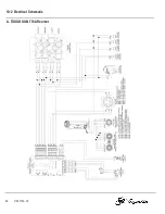
Page 31: ...e aware of the wire colors and their positions within the connector see section 10 2 Electrical Schematic on page 36 5 Remove the clamp limit switch fastener and remove assembly pull the wires through the grommet 6 Slide the two wires through the grommet into the TOUGH GUN Reamer 7 Fasten the new clamp limit switch into position 8 Install the two wires into the new keyed circuit board connector se...

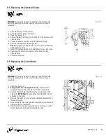
Page 32: ...sengage belt from the rear pulley 5 Release the air lines from the quick disconnect air fittings at the front of the motor 6 Pull the motor out IMPORTANT Be careful not to lose the belt tension spring 7 Reverse the order of the above steps for reassembly Figure 9 C 9 4 Replacing the Drive Belt WARNING Ensure air and power supply is off and disconnected before proceeding Please follow your facility...

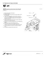
Page 33: ... the bottom of the solenoid valve 9 Close the rear cover Figure 9 D 9 6 Replacing the Circuit Board WARNING Ensure air and power supply is off and disconnected before proceeding Please follow your facility s lockout tagout procedures 1 Open the rear cover 2 Being careful not to damage the wiring Disconnect all wiring and remove the connectors from the circuit board 3 Remove the fasteners which sec...

Page 34: ...ay containment unit 2 Lift the spray containment cover out of the container 3 The baffle rests on the inside of the container and can be pulled out once the cover is removed 4 Remove the two 2 M5 SHCS on either side of the spray containment unit that secure it to the spray head 5 Lift the spray container straight up over the spray head to remove 6 Installation is the opposite of the removal proced...

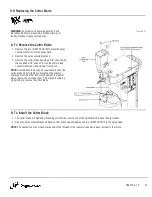
Page 35: ...above NOTE Considerable force may be required to loosen the cutter blade since it tightens naturally as the reamer operates Rest the 9 16 flat wrench against the reamer frame below the air connection This prevents slipping while trying to remove the cutter blade Figure 9 G B To Install the Cutter Blade 1 The cutter blade is installed by threading it clockwise into the top of the spindle shaft Reus...

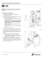
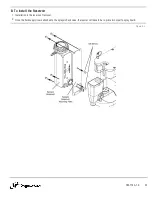
Page 36: ... the quick disconnect fitting see Figure 9 H d The fluid will begin to flow out of the supply line and into a container e Let the fluid drain until it stops 3 Open the rear cover of the reamer and disconnect the fluid level sensor two black wires with a 2 Pin connector on them 4 Remove the four 4 BHCS on the side of the reamer that hold the sprayer reservoir mounting plate onto the reamer see Figu...

Page 37: ...l the Reservoir 1 Installation is the reverse of removal 2 Once the fluid supply line is attached to the sprayer check valve the reamer will have to be re primed in order to spray liquid Figure 9 J OM TT4A 1 0 33 ...

Page 38: ... and spindle seal with a brush or with compressed air to eliminate blockages CLEAN Wipe clean any debris from the Nozzle Detect Proximity Sensor MONTHLY CHECK That the belt tension lock screw is securely tightened CHECK That the belt tension bolt is tightened CHECK The spindle unit for wear CHECK The solenoids and spool them to ensure there are no leaks and that they are operating properly CLEAN T...

Page 39: ...SECTION 10 TECHNICAL DATA 10 1 Pneumatic Diagrams A TOUGH GUN TT4A Reamer OM TT4A 1 0 35 ...

Page 40: ...10 2 Electrical Schematic A TOUGH GUN TT4A Reamer 36 OM TT4A 1 0 ...

Page 41: ... 10 TR 2661 Spindle seal 33 R 2240 Valve pack 11 TT4 500 20 TT4 reamer sprayer check valve assembly 34 R 2860 Reamer rear cover assembly 12 TT 2670 Reamer spindle cover 35 TT4 707 30 TT4 reamer TCP locator pin assembly 13 TT4 2110 TT4 reamer clamp cover 36 TR 2411 Spindle acuator 14 TR 2130 Clamp cylinder 37 See Section 7 6 Tregaskiss reamer cutter blade 15 TR 2120 Clamp jaw assembly 38 TT3E 2344 ...

Page 42: ...ation kit 3 WC 100 7 1 Wire cutter blade Qty 2 10 Non sellable SHCS M6x1x16mm long black oxide Qty 8 4 TT4 707 30 TT4 reamer TCP locator pin assembly 11 Non sellable SHCS M10x1 5x25mm long black oxide 5 TR 2221 Breather vent Qty 2 12 Non sellable SHCS M4x0 7x12mm long black oxide 6 TT3 2201 1 4 tubing 90 degree elbow uni fit thread Qty 3 13 Non sellable SHCS M8x1 25x65mm long 7 WC 100 31 Cylinder ...

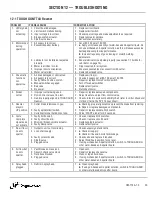
Page 43: ... 3 Gun improperly aligned in TOUGH GUN Reamer 1 Repair or replace damaged components 2 Adjust feed rate adjust flow control valve 3 Check v block nozzle compatibility chart refer to Cutter Blade and V Block Chart in the SP TT4 spec sheet 5 Reamer stays in UP position 1 Cutter blade is jammed in gun 2 Faulty spindle limit switch 3 Cycle Start signal held on too long 1 a Checking proper alignment ca...

Page 44: ...RRECTIVE ACTION 1 Over spray is excessive 1 Misalignment of gun 2 Gun not inserted into the spray containment unit far enough 3 Baffle not installed 1 Position the gun to be in the center of the opening on the spray containment unit 2 Insert gun to the depth specified in 8 2 Programming Events Sequence on page 24 3 Ensure that the internal baffle is installed properly 2 Fluid and debris are not dr...

Page 45: ...of bowl o ring 1 Replace bowl o ring Grease up before assembling 7 Air leaks from the drain cock 1 Foreign matter caught in the valve of the drain cock 2 Breakage of the seating part of the drain cock 1 Open the drain cock for a few seconds 2 Replace the bowl assembly 8 No drainage when the drain cock is open 1 Blockage of outlet of the drain cock due to solid foreign matter 1 Replace the bowl ass...

Page 46: ...ort Page Scan to view the TOUGH GUN TT4A Reamer Owner s Manual Scan to view the TOUGH GUN TT4 Reamer Spec Sheet Scan to view the TOUGH GUN Wire Cutter Owner s Manual Scan to view the TOUGH GARD Anti Spatter Multi Feed System Owner s Manual Scan to learn about TOUGH GARD Anti Spatter Liquid Scan to learn about Tregaskiss Robotic Air Cooled MIG Guns Tregaskiss 2570 North Talbot Road Windsor Ontario ...

Reviews: