SECTION 9 — MAINTENANCE
NOTE:
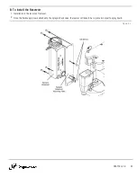
For ease of maintenance, the reamer can be removed from the welding environment and serviced in a proper maintenance area. Being
able to move the reamer around will assist in the replacement of some parts, such as the motor, spindle limit switch, solenoid valves, etc.
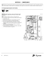
9-1 Replacing the Spindle Limit Switch
WARNING:
Ensure air and power supply is off and disconnected
before proceeding. Please follow your facility's lockout / tagout
procedures.
NOTE:
It may be necessary to remove or disconnect some
pneumatic tubing to access the required components and fasteners.
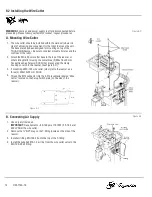
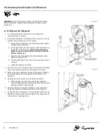
1. Open the rear cover.
2. Remove the two (2) lower 3-pin circuit board connectors.
3. Remove the one fastener on the limit switch bracket.
4. Remove assembly and replace with new part. Ensure the
actuator is clear of all limit switches when the new assembly is
installed.
5. Align the new bracket with the dowel holes on the reamer
frame face, then reinstall fastener.
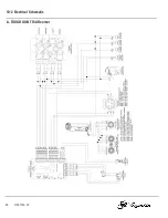
6. Plug in the tabbed 3-pin circuit board connectors (see section
10-2 Electrical Schematic on page 36).
Figure 9-A
26
OM-TT4A-1.0

