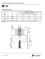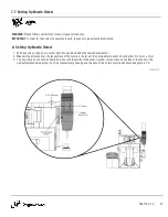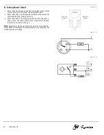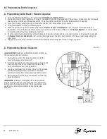
9-5 Replacing the Solenoid Valves
WARNING:
Ensure air and power supply is off and disconnected
before proceeding. Please follow your facility's lockout / tagout
procedures.
1. Shut off the power to the reamer.
2. Shut off the air supply to the reamer.
3. Open the rear cover.
4. Unplug the electrical connector directly from the bottom of the
solenoid valve.
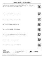
5. Loosen and remove the two (2) solenoid valve screws.
6. Remove the solenoid valve and gasket.
NOTE:
New gasket (included with new valve) must be installed
when replacing valve.
7. Install the new gasket and valve and tighten screws to 6 in-lbs.
8. Reconnect the electrical connector to the bottom of the
solenoid valve.
9. Close the rear cover.
Figure 9-D
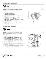
9-6 Replacing the Circuit Board
WARNING:
Ensure air and power supply is off and disconnected
before proceeding. Please follow your facility's lockout / tagout
procedures.
1. Open the rear cover.
2.
Being careful not to damage the wiring.
Disconnect all
wiring and remove the connectors from the circuit board.
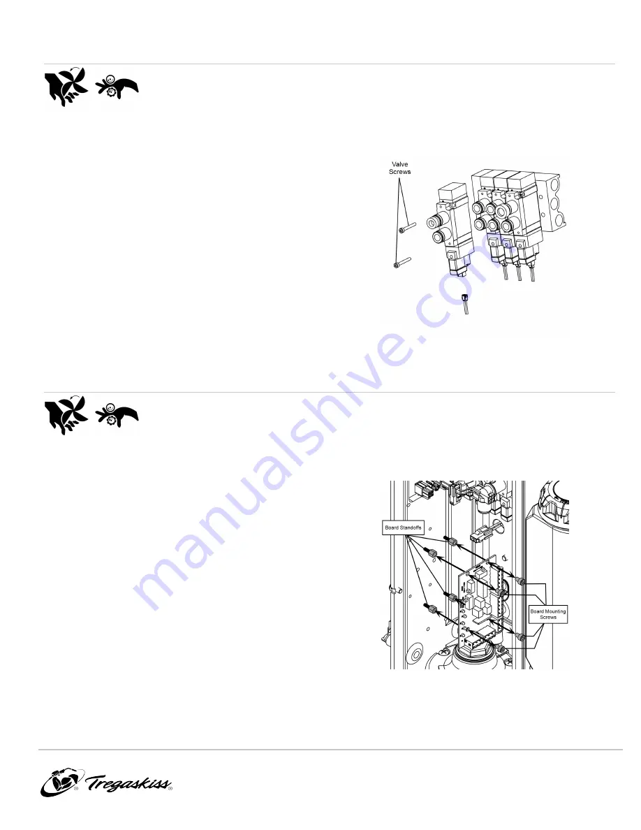
3. Remove the fasteners which secure the circuit board to the
standoffs.
IMPORTANT:
Ensure all four (4) standoffs are still
attached to the frame.
4. Remove the board from the unit and install the replacement in
the same position.
5. Once located in the proper position, secure the circuit board by
tightening the four fasteners.
6. Reconnect all wiring and reset sink/source switches to match
the configuration of the board that was removed.
Figure 9-E
OM-TT4A-1.0
29


