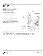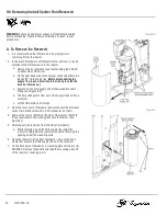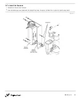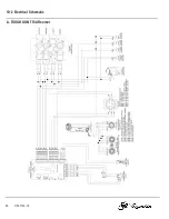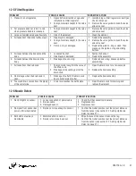
SECTION 12 — TROUBLESHOOTING
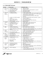
12-1 TOUGH GUN TT4A Reamer
PROBLEM
POSSIBLE CAUSE
CORRECTIVE ACTION
1. LED signals
not
activating.
1. Circuit board damaged.
2. Limit switch malfunctioning.
3. Input voltage is incorrect.
4. Broken switch actuator.
5. Sink/Source issue.
1. Replace circuit board.
2. Replace limit switch.
3. Check input voltage and make adjustments as required.
4. Replace actuator spindle.
5. Set switches accurately.
2. Motor stops
during
operation.
1. Air supply is incorrect.
2. Excessive spatter buildup.
3. Lubricator not installed or adjusted
properly.
4. Water in air lines / motor.
5. Improper nozzle orientation.
6. Motor valve failed.
1. Set at 80-100 psi at 16 CFM.
2.
a.
Apply or increase quantity of water-based anti-spatter liquid. Do
not use oil-based anti-spatter solution, as this will cause excessive
buildup and compromise performance.
b.
Increase frequency of gun cleaning or modify welding
parameters.
3. Ensure lubricator is adjusted properly (see section 7-1 Air Motor
4. Dryer required for air system.
5. Ensure consumables are concentric with cutter.
6. Replace damaged valve.
3. Pneumatic
functions
not
operative.
1. Air lines damaged or obstructed.
2. Air supply is incorrect.
3. Faulty Home Position switch.
4. Manual switches engaged.
5. Bad valve.
6. No power.
1. Replace air line(s).
2. Check air supply, set at 80-100 psi at 16 CFM.
3. Repair or replace Home Position switch.
4. Turn off manual switches.
5. Replace faulty valve.
6. Reconnect power.
4. Broken
cutter.
1. Improper cutter being used.
2. Flow control valve set too fast.
3. Gun improperly aligned in TOUGH GUN
Reamer.
1. Repair or replace damaged components.
2. Adjust feed rate, adjust flow control valve.
3. Check v-block / nozzle compatibility chart (refer to
Cutter Blade and
V-Block Chart
in the SP-TT4 spec sheet).
5. Reamer
stays in
UP position.
1. Cutter blade is jammed in gun.
2. Faulty spindle limit switch.
3. Cycle Start signal held on too long.
1.
a.
Checking proper alignment can prevent the blade from jamming.
b.
Repair or replace damaged components.
2. Repair or replace spindle limit switch.
3. Pulse 'START' signal for 0.5 seconds.
6. Cycle
Complete
signal does
not activate.
1. Faulty limit switch.
2. Faulty circuit board.
3. Missing / broken spindle actuator.
4. Faulty clamp valve.
1. Check or replace limit switches.
2. Check or replace circuit board.
3. Replace spindle actuator.
4. Replace faulty valve.
7. No air flow /
no anti-
spatter.
1. Output to unit not functioning.
2. Loss of air supply.
3. Faulty solenoid valve.
4. Sink/Source.
5. Plugged valve.
1. Check output signal and cable.
2.
a.
Check air supply.
b.
Check air line and nozzle for blockage.
3. Check valve and replace if required.
4. Adjust Sink/Source switch for sprayer.
5. If using oil-based anti-spatter solution, switch to TOUGH GARD or
other water-based anti-spatter liquid.
8. Air flow but
no anti-
spatter.
1. Vent blocked on reservoir.
2. Spool in check valve stuck.
3. Fluid hose blocked.
4. Plugged valve.
1. Open vent.
2. Repair or replace check valve.
3. Clean or repair fluid hose.
4. If using oil-based anti-spatter solution, switch to TOUGH GARD or
other water-based anti-spatter liquid.
9. Spray head
plugged.
1. Debris in spray head.
1.
a.
Clean spray head.
b.
If using oil-based anti-spatter solution, switch to TOUGH GARD
or other water-based anti-spatter liquid.
OM-TT4A-1.0
39

