background image

Summary of Contents for PRIMUS 400

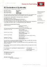
Page 1: ...Operating manual ID number 244156V03 Machine type 6900 6910 Language English Translation of the original operating manual PRIMUS 400 PRIMUS smart PRIMUS 400 Black Edition PRIMUS smart Black Edition...

Page 2: ......

Page 3: ......

Page 4: ......

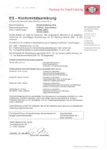
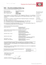
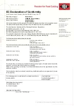
Page 5: ...licable such as DIN EN ISO 12100 2013 08 Safety of machinery General principles for design Risk assessment and risk reduction DIN EN ISO 13849 1 2016 06 Safety of machinery Safety related parts of con...

Page 6: ...such as DIN EN ISO 12100 2013 08 Safety of machinery General principles for design Risk assessment and risk reduction DIN EN ISO 13849 1 2016 06 Safety of machinery Safety related parts of control sy...

Page 7: ......

Page 8: ...ho does what 13 2 5 Information signs on the machine 14 2 6 Placement of the information signs 15 2 7 Placement of rating plate and electrical wiring diagram 17 2 8 Safety instructions 18 2 8 1 Genera...

Page 9: ...7 2 Initialisation 49 7 3 Product length 49 7 4 Inserting and cutting product 50 7 4 1 Inserting the product 50 7 4 2 Slicing the product 51 7 4 3 Cutting a pre selected number of slices 52 7 4 4 Halv...

Page 10: ...otective equipment 90 10 3 Maintenance overview 91 10 4 Visual inspection of seal 91 10 5 Sharpening the blade 92 11 Help and Service 95 11 1 Your service partner 96 11 2 If any fault occurs 97 12 Dis...

Page 11: ...Table of contents Table of contents 07 2019 244156V03_EN...

Page 12: ...his operating manual before starting any work The operating manual is the basis for all actions and all training on the machine Furthermore the applicable national accident prevention regulations and...

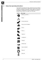
Page 13: ...within a chapter provide cross references to information in other chapters An overview of the chapters is provided below For easier orientation the symbols are specified that you will find in the hea...

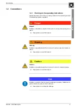
Page 14: ...in serious personal injuries or death Description to avoid the hazard Warning Warning Indicates a possible hazard that can result in serious personal injuries or death Description to avoid the hazard...

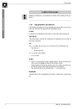
Page 15: ...he subdivision into chapters and is not part of the table of contents List Two symbols are used in a list in continuous text according to use First level list Second level list A is used in lists in t...

Page 16: ...obligations in the supply contract the General Terms and Con ditions and the manufacturer s Terms and Conditions of Sale and Delivery and the applicable statutory regulations at the time of the contra...

Page 17: ...he making of copies whether in whole or in part is expressly only au thorised for the owner for internal use in connection with the operation of the machine The TREIF company reserves the right for pe...

Page 18: ...fety instructions NOTICE Create operating instruction The operator is obliged to produce operating instructions that define the responsibilities for working on and with the machine This chapter covers...

Page 19: ...tended use The content of the crumb tray is unfit for consumption and must not be returned to the food process 2 2 Foreseeable misuse Never operate the machine in potentially explosive atmospheres Non...

Page 20: ...s for the persons who work on the machine These instructions must take account of the qualification experience technical knowledge and the physical sensory and mental capabilities of the persons entru...

Page 21: ...Notify TREIF in writing about the sale or loan The owner of the machine must effectively prevent people from work ing on or with the machine while people are present in the danger zone who are under...

Page 22: ...in the operating instructions for the operation of the machine at the op erating site The personnel must be aware of the assigned responsibilities for the operation maintenance setting up and cleaning...

Page 23: ...se technical training knowledge and ex perience as well as knowledge of the pertinent regulations renders them capable of properly carrying out work on electrical systems independently identifying pos...

Page 24: ...led electricians are qualified to carry out work on electrical sys tems 5 Maintenance work limited to a function check of the safety elements before beginning working on the machine may also be carrie...

Page 25: ...nger be identified if these information signs are missing or illegible Missing or illegible information signs can be reordered Article number Symbol Description 49720 Electric shock 49719 Cutting haza...

Page 26: ...information signs AUDIBLY ENGAGE LATCHING are located on the front side of the removal chute 2 In the blade box there is the information sign BLADE CHANGE 3 The information signs CUTTING INJURY and W...

Page 27: ...ent of the information signs 16 07 2019 244156V03_EN 5 The information sign ERROR MESSAGES is located on the inside of the door 6 The information sigh BLADE SHARPENING SERVICE is located on the inside...

Page 28: ...r cover directly in front of the electrical control A non instructed person is at risk of sustaining injuries from electric shock Disconnect the main power supply and secure against unintentional swit...

Page 29: ...the fault has been eliminated by an authorised person TREIF ser vice personnel if necessary 2 8 2 Machine specific safety information CAUTION Risk of injury on the upright knife Risk of sustaining cu...

Page 30: ...er with tumbler the infeed cover is held shut by a lock during operation A malfunction is present if the cover can still be opened dur ing operation All movements within the machine are stopped immedi...

Page 31: ...Safety Safety layout 20 07 2019 244156V03_EN...

Page 32: ...r TREIF machine is summarised in this chapter If you require more information or have any questions please con tact your TREIF sales partner directly Your service partner on page 96 This chapter cover...

Page 33: ...56V03_EN 0 1 2 3 4 5 6 7 8 9 10 11 12 13 14 3 1 The machine at a glance 3 1 1 General overview 1 Front door interlock 2 Infeed cover 3 Bagging plate 4 Control panel 5 Holder for bread bags 6 Master sw...

Page 34: ...roduct information The machine at a glance 07 2019 244156V03_EN 23 0 1 2 3 4 5 6 7 8 9 10 11 12 13 14 1 Removal chute interlock 2x 2 Removal chute 3 Front door 4 Blade 5 Crumb tray 2 1 1 3 5 4 AR1009...

Page 35: ...Product information The machine at a glance 24 07 2019 244156V03_EN 0 1 2 3 4 5 6 7 8 9 10 11 12 13 14 1 Removal chute 2 Slice support 3 Blade chute 4 Infeed chute 5 Product feed holder...

Page 36: ...244156V03_EN 25 0 1 2 3 4 5 6 7 8 9 10 11 12 13 14 3 2 The control panel 1 Display 2 START STOP eco button section per minute on page 59 3 Rotary switch 4 START STOP button section per minute on page...

Page 37: ...00 350 mm Max insertion cross section W x H 330 x 150 330 x 150 330 x 150 mm Max length in the removal chamber 400 400 350 mm Cut off length 4 24 4 24 4 24 mm Slices per minute 130 eco 220 130 eco 220...

Page 38: ...Product information Dimensional drawing 07 2019 244156V03_EN 27 0 1 2 3 4 5 6 7 8 9 10 11 12 13 14 3 4 Dimensional drawing 3 4 1 Dimension sheet PRIMUS 400...

Page 39: ...Product information Dimensional drawing 28 07 2019 244156V03_EN 0 1 2 3 4 5 6 7 8 9 10 11 12 13 14 3 4 2 Dimension sheet PRIMUS smart...

Page 40: ...29 Transport and unpacking 30 Installation and connection 31 4 1 Safety information about transport WARNING Danger to life from machine tipping over The machine can topple over due to incorrect trans...

Page 41: ...he machine The machine is transported from the factory in secure packaging 1 Remove the packaging and examine the machine for any possible transport damage Submit a written complaint to the carrier im...

Page 42: ...be provided by the customer Check whether the operating voltage stated on the rating plate corre sponds to the voltage of your mains power supply 2 The maximum permitted difference is 5 The machine mu...

Page 43: ...Transport and installation Installation and connection 32 07 2019 244156V03_EN...

Page 44: ...main power supply must be interrupted and secured against unintend ed switching on again during all installation work on the machine as soon as the type of work allows to do so Unplug the mains plug...

Page 45: ...res that the blade is in the replacement position bottom position 2 Open the infeed cover Opening feeding lid on page 80 3 Switch off the mains power disconnecter master switch 4 Open the front door O...

Page 46: ...knife NOTICE When using the fastening nut that was previously used to fasten the blade it cannot be ensured that the clamping force is still sufficient The blade could become detached and damage the...

Page 47: ...ont door on page 87 5 3 1 Checking that the knife runs freely 1 The machine is operational 2 Select the Service menu via the rotary pushbutton Men Ser vice on page 68 The cleaning function is displaye...

Page 48: ...or with the machine This chapter covers the following Safety instructions for start up 38 Start ups 39 Functional test of the safety switches 41 Switch off 45 NOTICE Create operating instruction The o...

Page 49: ...knife The cut off knife is very sharp There is increased risk of injury in the case of unsafe handling of the cut off knife Wear personal protective equipment Only place dismantled blades in a safe pl...

Page 50: ...s been delivered The machine must have been completely installed Details can be found in chapter Installation and connection on page 31 and below Installation includes Unpacking the machine Assembling...

Page 51: ...function test of the safety switches Functional test of the safety switches on page 41 The machine is operational 6 2 3 Start up after an EMERGENCY STOP The start up after EMERGENCY STOP is performed...

Page 52: ...test of all safety devices daily before every start up Check the function of the safety switches after all cleaning mainte nance or repair work Do not operate the machine if it does not switch off wi...

Page 53: ...eed cover 2 Press the START STOP button The cutting process must not start no blade rotation an error mes sage is displayed There is a malfunction if the cutting process starts TEST 2 1 Close the infe...

Page 54: ...g on Also unplug and secure the mains plug Only restart the machine when this error has been remedied by TREIF Customer Service 1 Press the START STOP button The cutting process begins blade rotation...

Page 55: ...Also unplug and secure the mains plug Only restart the machine when this error has been remedied by TREIF Customer Service The machine is operational 1 Perform an initialisation Initialisation on page...

Page 56: ...RGENCY STOP CAUTION Risk of injury on the upright knife If you open any cover or the blade box cover during a running cutting op eration the machine will switch off and the blade will stop immediately...

Page 57: ...Start up Switch off 46 07 2019 244156V03_EN...

Page 58: ...ine This chapter covers the following Safety instructions for operation 48 Initialisation 49 Product length 49 Inserting and cutting product 50 Halving the product 53 Slice product half with previousl...

Page 59: ...ht knife If you open any cover or the blade box cover during a running cutting op eration the machine will switch off and the blade will stop immediately The blade can come to a stop in the chute and...

Page 60: ...hen clockwise The product feed holder moves back to the clamping position 5 The machine is operational 7 3 Product length ADDITIONAL INFORMATION If the product is longer than the insertion chamber you...

Page 61: ...inst the product feed holder 3 When cutting half a round loaf of bread place the cutting surface against the chamber wall in the direction of the operator prevents wedge shaped bread slices 4 Raise th...

Page 62: ...ary pushbutton switch clockwise a increases the slice thickness Turning the rotary pushbutton counterclockwise b reduces the slice thickness 3 Press the desired START STOP button START STOP eco button...

Page 63: ...the slice thickness 3 Press 1 the rotary pushbutton The halving mode is selected 4 Turning the rotary pushbutton clockwise a increases the number of slices to be cut 5 Turning the rotary pushbutton c...

Page 64: ...is in clamping posi tion ADDITIONAL INFORMATION You can cut the part product that is still in the insertion chamber directly 1 Insert the product Inserting the product on page 50 2 Press the rotary p...

Page 65: ...Press the rotary pushbutton The machine switches to halving mode 3 Position the product by turning the rotary button clockwise b so that the product is centred above the blade chute and divided centra...

Page 66: ...ting the product on page 50 2 Set the desired slice thickness by turning the rotary pushbutton 3 Press the rotary pushbutton The machine switches to halving mode 4 Turn the rotary switch anticlockwise...

Page 67: ...ce thickness can be disabled by setting the value 0 Setting and saving the basic slice thickness 1 Set the desired basic slice thickness by turning the rotary pushbutton The set basic slice thickness...

Page 68: ...behind the product feed holder The slice thickness is uneven The product is too soft or too fresh Let the product stand for a few hours Blade is blunt Replace the blade The product is not held tight b...

Page 69: ...Operation If a malfunction occurs 58 07 2019 244156V03_EN...

Page 70: ...nu General 70 Additional information on the display 71 8 1 General information about the display and accessing visualisation The display is used to show the menu pages The Treif logo will first appear...

Page 71: ...n menu is used to select the individual cutting modes The follow ing cutting modes can be selected Full cutting mode i e the entire bread is sliced with a defined slice thickness Halving mode i e the...

Page 72: ...the sub function Slice mode is selected Turning the rotary pushbutton counterclockwise the sub function Slice product half is selected The sub function Slice mode is selected The set slice thickness i...

Page 73: ...t 3 seconds The menu bar 1 appears in the left area of the main menu The following menus can be accessed via the menu bar Symbol Function Jumping back to the higher level menu structure and closing th...

Page 74: ...he corresponding menu symbol by turning the rotary pushbut ton The green border indicates which menu symbol is selected At the same time the selected menu is shown in the display but no entries can be...

Page 75: ...e thick ness The other menus are closed in the same way 1 Press the rotary pushbutton The menu is locked The menu bar is highlighted in black and lock ing of the menu is indicated by the green frame a...

Page 76: ...plies only to this one cutting process The set basic slice thickness is active again after the cutting process is completed ADDITIONAL INFORMATION The basic slice thickness can be disabled by setting...

Page 77: ...The individual pages can be accessed by turning the rotary pushbutton Some of the displays listed below are also shown on the start screen during initialisation of the machine Page 59 Menu Statistics...

Page 78: ...cs page 2 Page 2 of the menu Statistics shows the following counters Indicator Explanation Time passed since last cleaning Time until next cleaning Display of current blade wear Blade OK Blade change...

Page 79: ...the blade in an unsafe manner Wear personal protective equipment Never touch the blade s cutting edge Make sure that no unauthorised persons have access to the knife Movement of the blade to the clean...

Page 80: ...he blade to a changed cleaning position al ternative In addition you can also move the blade automatically to a changed clean ing position 1 Close the infeed cover 2 Press one of the start stop button...

Page 81: ...sed by turning the rotary pushbutton Menu General page 1 Page 1 of the menu General shows the following machine specifications Indicator Explanation Display of the software version Display of the dist...

Page 82: ...mation on the display The information below may be displayed on the main menu depending on the machine condition Presentation Function Display during a cutting operation The currently selected cutting...

Page 83: ...corresponding warning code Display of information with corresponding info code Display that the automatic test of the brake function is carried out Display that the automatic test of the brake functio...

Page 84: ...Visualisation Additional information on the display 07 2019 244156V03_EN 73 Prompt to swivel the removal chute up after cleaning is completed Presentation Function...

Page 85: ...Visualisation Additional information on the display 74 07 2019 244156V03_EN...

Page 86: ...pter describes the steps and instructions for daily cleaning This chapter covers the following Safety instructions for cleaning 76 Cleaning position for blade 78 Preparation for complete cleaning 80 I...

Page 87: ...touching the blades cutting edge is not pos sible Wear personal protective equipment CAUTION Risk of injury during cleaning Various machine assemblies are exposed for cleaning that can present a dang...

Page 88: ...UTION Risk of injury on the product holder Hands or fingers in the operating range of the product feed holder can be injured during closing or opening Make sure that hands and fingers are not in the d...

Page 89: ...fitted Never touch the blade s cutting edge Make sure that no unauthorised persons have access to the knife Automatic movement of the blade to the cleaning position 1 Close the infeed cover The blade...

Page 90: ...r cleaning has been performed the blade must be moved to its working position 1 Close the infeed cover 2 Press the STOP button and keep it pressed for approx 5 seconds The blade leaves its cleaning po...

Page 91: ...e rollers engage in the upper end position You now have access to the work area Folding the infeed cover The lid can be folded to clean the rear side of the feeding lid 1 Fold the upper end b of the i...

Page 92: ...slowly lower the removal chute 2 down towards the rear Attaching the blade guard The blade guard must be attached before removing and inserting the crumb tray 1 Open the front door of the machine Open...

Page 93: ...Use a hand brush to remove product scraps and crumbs Use a brush to remove product residues from the product feed holder Clean the blade only with a moist lint free cloth Dry the blade thoroughly aft...

Page 94: ...es to single shift operation CAUTION Risk of injury on the product holder Risk of injury on the tips and claws of the product feed holder Always wear the personal protective equipment when working on...

Page 95: ...ith a damp lint free and clean cloth until the deposits on the blade and cutting edge have been removed Avoid the formation of droplets Now dry the blade To completely clean the blade you need to repe...

Page 96: ...tep Switch on the machine master switch in the 1 ON position 15 Step Perform an initialisation page 49 16 Step Now carry out a function test of the safety switches Functional test of the safety switch...

Page 97: ...e removal chute 1 to the top end position working position and hold it in this position from underneath with one hand 2 Secure the two locks so that the removal chamber is held securely Inserting crum...

Page 98: ...side and close the front door completely 3 Press the handle 3 completely to lock the front door Turning over and closing feeding lid After cleaning the inside of the feeding lid this must be folded b...

Page 99: ...eaning process The safety signs must be legible and complete Replace any missing or illegible safety signs Final inspection 1 Check the safety signs after each cleaning An overview of the safety signs...

Page 100: ...You can find a template for the maintenance record in the chapter Appendix This chapter covers the following Safety instructions for maintenance 89 Personal protective equipment 90 Maintenance overvie...

Page 101: ...in the case of defective safety de vices defective covers or lids defective switches or buttons Check the function of the safety switches after all cleaning mainte nance or repair work Do not operate...

Page 102: ...ours every 4 years Power cable and plug X Visual inspection replace in the case of damage Hoods door and cov ers X Visual inspection replace in the case of damage Blade X Check for wear and damage suc...

Page 103: ...blade s cutting edge Make sure that no unauthorised persons have access to the knife ADDITIONAL INFORMATION We recommend keeping a second replacement blade in stock in order to prevent downtimes of t...

Page 104: ...Maintenance Sharpening the blade 07 2019 244156V03_EN 93...

Page 105: ...Maintenance Sharpening the blade 94 07 2019 244156V03_EN...

Page 106: ...and Service 11 Help and Service This chapter provides you with additional information about service as well as troubleshooting This chapter covers the following Your service partner 96 If any fault oc...

Page 107: ...rvice package from start up and induction on the machine to training of the operating personnel including individual ser vice and maintenance contracts to IT supported remote maintenance for your mach...

Page 108: ...the slice support to the start ing position remove any product residues if necessary Slice support is bent Replace slice support if necessary Sensor defective Contact TREIF Service The product feed h...

Page 109: ...Help and Service If any fault occurs 98 07 2019 244156V03_EN...

Page 110: ...99 Disposal 12 Disposal This chapter provides you with the necessary information on the disposal of your end of life device This chapter covers the following Decommissioning 100 Disposal 99...

Page 111: ...ng and disposal must be complied with for all work activities In the event of doubt ask the manufacturer or obtain information about environmentally compatible disposal from the local authorities or s...

Page 112: ...he following Proof of training 101 Maintenance record 102 13 1 Proof of training In your capacity as the owner obtain confirmation from your operating and maintenance personnel in the table below that...

Page 113: ...6V03_EN 13 2 Maintenance record In your capacity as the owner obtain confirmation from your maintenance personnel in the table below that the maintenance work and function checks have been performed M...

Page 114: ...Chapter 4 Claim for damages 6 Cleaning blade in installed condition 78 Cleaning position for blade 78 Condition 10 Conformity 1 Conventions 4 Crumb tray 36 D Date of manufacture 1 Drugs 11 F Feeding...

Page 115: ...manual 1 P Personnel deployment 9 Positioning the product 54 Pressure plate 34 Protection 7 Q qualification 9 R Responsibilities 11 Ring spanner 34 risk conscious 9 S Safety labels 84 88 Safety switch...

Page 116: ...Index 07 2019 244156V03_EN 105 W Workplace lighting 10...

Page 117: ...Index 106 07 2019 244156V03_EN...

Reviews: